Percutaneous spinal implants and methods

a technology of spinal implants and implants, applied in the field of spinal conditions, can solve the problems of increased chance of significant complications, loss of bladder or bowel function, or paralysis,

Active Publication Date: 2007-02-22
MEDTRONIC EURO SARL
View PDF99 Cites 409 Cited by
  • Summary
  • Abstract
  • Description
  • Claims
  • Application Information

AI Technical Summary

Problems solved by technology

Spinal stenosis can cause pain, weakness, numbness, burning sensations, tingling, and in particularly severe cases, may cause loss of bladder or bowel function, or paralysis.
This procedure, however, may result in blood loss and an increased chance of sign...

Method used


Image

  • Percutaneous spinal implants and methods
  • Percutaneous spinal implants and methods
  • Percutaneous spinal implants and methods

Examples


Embodiment Construction

[0144] As used in this specification and the appended claims, the singular forms “a,”“an” and “the” include plural referents unless the context clearly dictates otherwise. Thus, for example, the term “a member” is intended to mean a single member or a combination of members, “a material” is intended to mean one or more materials, or a combination thereof. Furthermore, the words “proximal” and “distal38 refer to direction closer to and away from, respectively, an operator (e.g., surgeon, physician, nurse, technician, etc.) who would insert the medical device into the patient, with the tip-end (i.e., distal end) of the device inserted inside a patient's body first. Thus, for example, the implant end first inserted inside the patient's body would be the distal end of the implant, while the implant end to last enter the patient's body would be the proximal end of the implant.

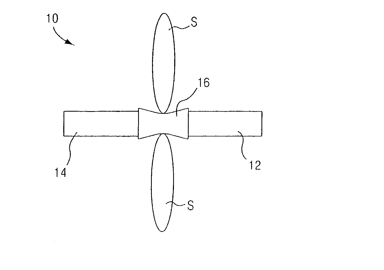
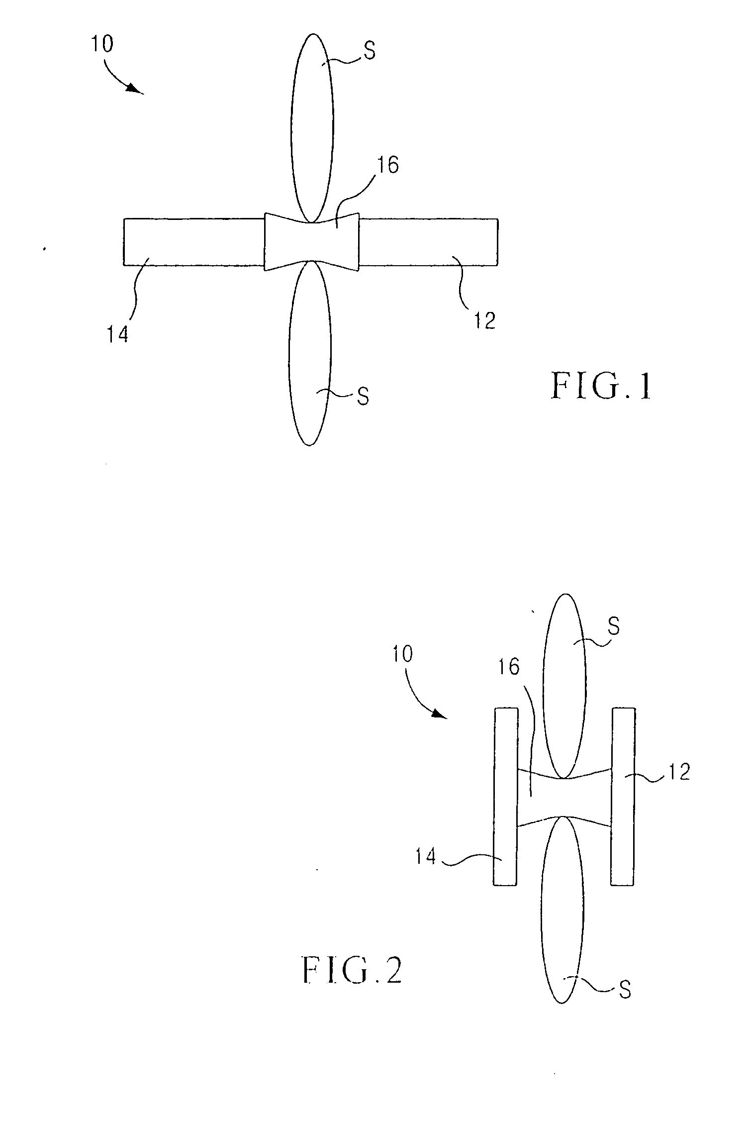
[0145] In one embodiment, apparatus includes an elongate member having a proximal portion configured to be defor...


PUM


Abstract

An apparatus includes an elongate member having a portion configured to be deformed from a first configuration to a second configuration. In one variation, the apparatus includes an outer body, defining an interior region, and an inner body. A portion of the outer body is configured to be disposed between adjacent spinous processes. The inner body is disposed within the interior region of the outer body. A distal end portion of the inner body is coupled to a distal end portion of the outer body. A proximal end portion of the inner body configured to removably receive a tool to move the outer body between a collapsed configuration and an expanded configuration.

Description

CROSS-REFERENCE TO RELATED APPLICATIONS [0001] This application is a continuation-in-part of International Patent Application No. PCT / US2006 / 005580, entitled “Percutaneous Spinal Implants and Methods,” filed Feb. 17, 2006; which claims priority to U.S. patent application Ser. No. 11 / 059,526, entitled “Apparatus and Method for Treatment of Spinal Conditions,” filed Feb. 17, 2005; U.S. Provisional Application Ser. No. 60 / 695,836 entitled “Percutaneous Spinal Implants and Methods,” filed Jul. 1, 2005; U.S. patent application Ser. No. 11 / 252,879, entitled “Percutaneous Spinal Implants and Methods,” filed Oct. 19, 2005; and U.S. patent application Ser. No. 11 / 252,880, entitled “Percutaneous Spinal Implants and Methods,” field Oct. 19, 2005, each of which are incorporated herein by reference in its entirety. [0002] This application is related to U.S. patent application Ser. Nos. 11 / 356,301, 11 / 356,302, 11 / 356,296, 11 / 356,295 and 11 / 356,294, each entitled “Percutaneous Spinal Implants and ...

Claims


Application Information

Patent Timeline
IPC IPC(8): A61F2/30
CPCA61B17/025A61B17/7062A61B2017/0256A61B2017/00557A61B17/7065
Inventor MALANDAIN, HUGUES F.EDIDIN, AVRAM ALLANKOHM, ANDREW C.
Owner MEDTRONIC EURO SARL
Why Eureka
Try Eureka