System and method for testing the integrity of a vehicle testing/diagnostic system

a vehicle testing and diagnostic system technology, applied in repeater circuits, line-transmission details, instruments, etc., can solve problems such as failure of known diagnostic systems and incorrect classification of vehicles

Inactive Publication Date: 2007-02-22
ENVIROTEST SYST HLDG CORP
View PDF14 Cites 38 Cited by
  • Summary
  • Abstract
  • Description
  • Claims
  • Application Information

AI Technical Summary

Benefits of technology

[0016] Each of the one or more predetermined protocols may not implement all of the connections (e.g., pins, cavities, etc.) formed between the vehicle testing / diagnostic system and the integrity testing system via the connector. As such, the receiving module may group the signals transmitted by the vehicle testing / diagnostic system via the connector in accordance with the one or more predetermined communications protocols. For example, in instances wherein the connector includes a standard sixteen cavity data link connector, if a given communications protocol implements only cavities 4 and 12, then the receiving module may group the signals received by the integrity system on cavities 4 and 12 of the connector.
[0017] Based on the signals received by the receiving module, the determination module may determine whether the vehicle testing / diagnostic system is capable of communicating via the one or more predetermined communications protocols. For instance, in the example of the given communications protocol that implements cavities 4 and 12, if the receiving module receives signals from the vehicle testing / diagnostic system via cavities 4 and 12 of the connector, then the determination module may determine that the vehicle testing / diagnostic system is capable of communicating via this given communications protocol. However, if a second given communications protocol implements cavities 3 and 8, and the receiving module does not receive a signal from the vehicle testing / diagnostic system via cavity 8, then the determination module may determine that the vehicle testing / diagnostic system is not capable of communicating via the second communications protocol.
[0018] The results / display module may convey the determinations of the determination module to a user. For example, the results module may graphically display (e.g., via one or more lights, a display screen, or other visual display) the determinations of the determination module. In other implementations, the results / display module may use other mechanisms for conveying the determinations (e.g., sounds, etc.). In some instances, the results / display module may convey a determination about each of the predetermined communications protocols separately. For instance, in the example provided above, the results / display module may convey that the vehicle testing / diagnostic system is capable of communicating via the first given communications protocol but is not capable of communicating via the second given protocol.

Problems solved by technology

However, should the vehicle testing / diagnostic system be unable to communicate with the OBD upon connection due to a malfunction associated with the OBD system, or for other reasons, the vehicle may be classified as a “fail.” Some conventional emission testing systems may be incapable of detecting instances wherein a failure to communicate between the vehicle testing / diagnostic system and the OBD may be caused by a malfunction associated with the testing station (e.g., a faulty DLC associated with the vehicle testing / diagnostic system) rather than a malfunction associated with the OBD system.
Consequently, in cases wherein a malfunction may be present at the testing station, vehicles may be incorrectly classified as “fails” with respect to meeting emissions standards.
Similarly, known diagnostic systems may not be capable of determining instances in which a failure to communicate with an OBD system may be due to faulty diagnostic equipment, as opposed to a faulty OBD system.
These and other drawbacks exist with conventional diagnostic and testing systems that communicate with OBD systems.

Method used


Image

  • System and method for testing the integrity of a vehicle testing/diagnostic system
  • System and method for testing the integrity of a vehicle testing/diagnostic system
  • System and method for testing the integrity of a vehicle testing/diagnostic system

Examples


Embodiment Construction

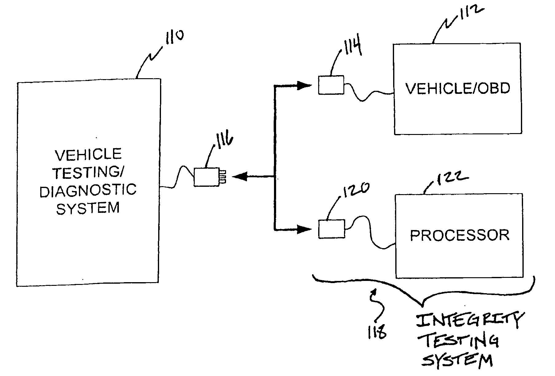
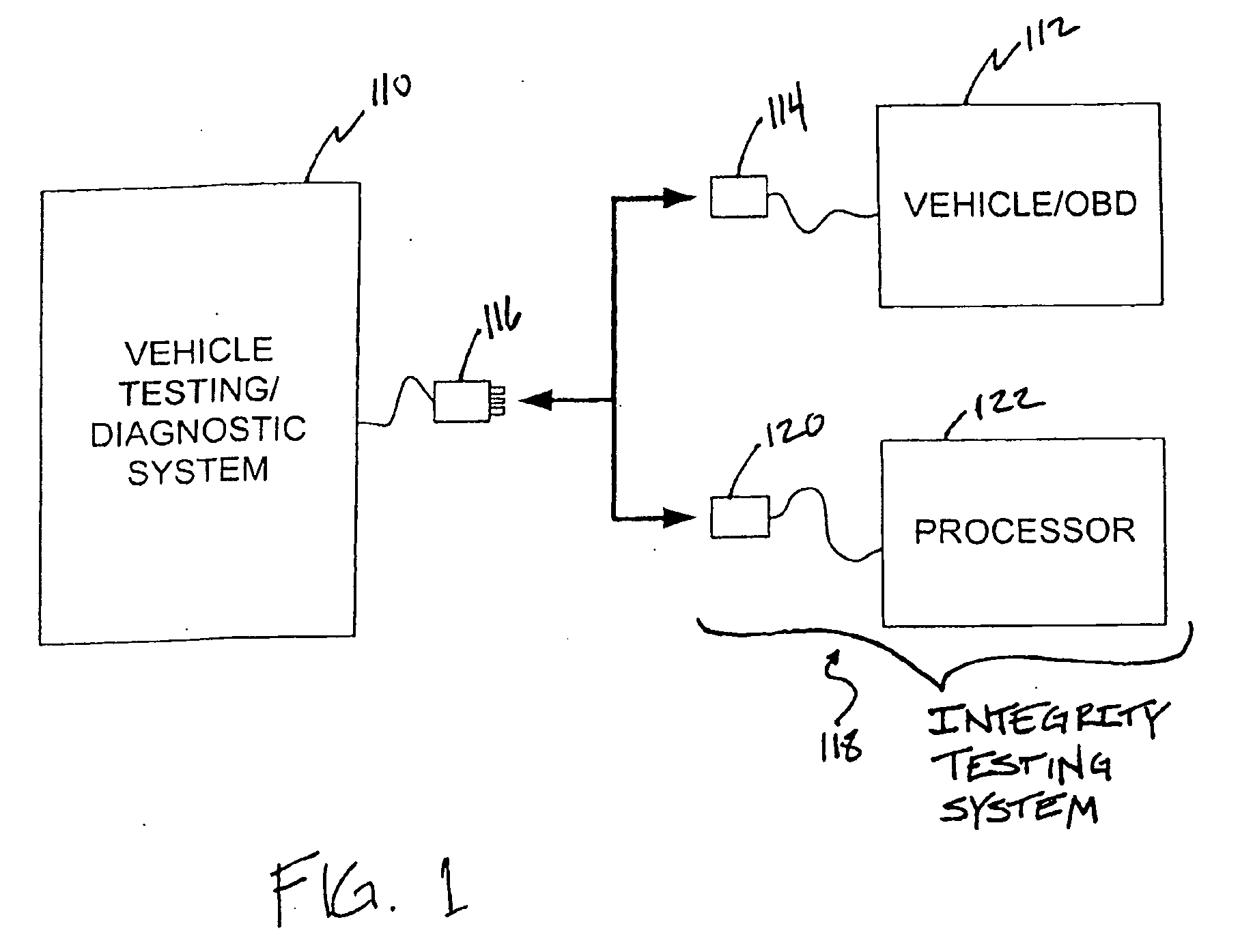
[0032]FIG. 1 illustrates a vehicle testing / diagnostic system 110 capable of communicating with an OBD system 112 on board a vehicle.

[0033] Vehicle testing / diagnostic system 110 may, for example, comprise any equipment (portable or stationary) found in an automotive maintenance and / or testing (e.g., centralized or decentralized) environment (e.g., a test lane, garage bay, open-air test area, etc.) or other environment capable of communicating with an OBD system.

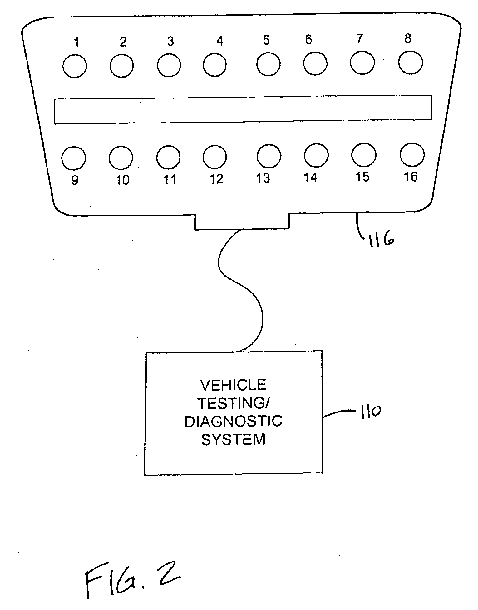
[0034] Vehicle OBD system 112 may include a sixteen cavity data link connector 114. System 110 may include a sixteen pin data link connector 116 capable of interfacing with connector 114 to form an operative communication link between system 110 and vehicle OBD system 112. Information may be transmitted over this communications link from vehicle OBD system 112 to system 110, or vice versa. The information transmitted to system 110 may include trouble codes that are set and / or not set on vehicle OBD system 112, diagnostic inf...


PUM


Abstract

A system and method for testing the integrity of a vehicle testing/diagnostic system is provided. Examples of vehicle testing/diagnostic systems may include any equipment (portable or stationary) found in an automotive maintenance and/or testing environment (or other environment) that is capable of communicating with vehicle on-board diagnostic (OBD) systems. Prior to conducting an OBD test on one or more vehicles, an integrity testing system interfaces with a vehicle testing/diagnostic system to determine whether the vehicle testing/diagnostic system is capable of communicating via one or more predetermined communications protocols.

Description

CROSS-REFERENCE TO RELATED APPLICATIONS [0001] This Application claims priority to U.S. Provisional Patent Application Ser. No. 60 / 709,117, filed Aug. 18, 2005, which is incorporated herein by reference in its entirety.FIELD OF THE INVENTION [0002] The invention relates to testing the integrity of a vehicle testing / diagnostic system used to communicate with an on board diagnostic system of a vehicle. BACKGROUND OF THE INVENTION [0003] The Environmental Protection Agency (EPA) requires vehicle manufacturers to install on-board diagnostic (OBD) systems for emission control on their light-duty automobiles and trucks beginning with model year 1996. OBD systems typically monitor vehicle emission control systems to detect any malfunction or deterioration that may cause emissions to exceed certain thresholds, such as state-mandated emission requirements or other thresholds. In conventional OBD systems, all (or substantially all) information monitored and / or calculated by an OBD system may ...

Claims


Application Information

Patent Timeline
Patent Type & Authority Applications(United States)
IPC IPC(8): G06F19/00
CPCG01R31/007G06F11/2215G07C5/008G07C2205/02
Inventor AVERY, DONALD JACKSONGORETTI, TERRY EDWARD
Owner ENVIROTEST SYST HLDG CORP
Why Eureka
Try Eureka