Drive system for aircraft landing gear

a technology for driving systems and landing gears, which is applied in the direction of gearing, gearing details, hoisting equipment, etc., can solve the problems of cyclical variations, uneven torque transfer from the drive pinion to the driven gear, and roller gear rotational speed variations

Active Publication Date: 2017-02-23
AIRBUS OPERATIONS LTD
View PDF0 Cites 0 Cited by
  • Summary
  • Abstract
  • Description
  • Claims
  • Application Information

AI Technical Summary

Benefits of technology

[0021]In preferred embodiments the drive system is switchable between the drive configuration and a neutral configuration in which the drive pinion is not capable of meshing with the driven gear. In this way, the wheel can rotate freely with the drive system is not engaged, for example during take-off and landing of the aircraft.

Problems solved by technology

However, the inventor has identified that a problem with a sprocket-roller gear arrangement is that a variation in roller gear rotational speed occurs with each tooth to roller engagement and disengagement.
That is, the torque transfer from the drive pinion to the driven gear is not smooth, but is instead subject to cyclical variations.
This torque / velocity variation, or transmission error, may lead to undesirable vibration within the landing gear during operation of the drive system.

Method used


Image

  • Drive system for aircraft landing gear
  • Drive system for aircraft landing gear
  • Drive system for aircraft landing gear

Examples


Embodiment Construction

)

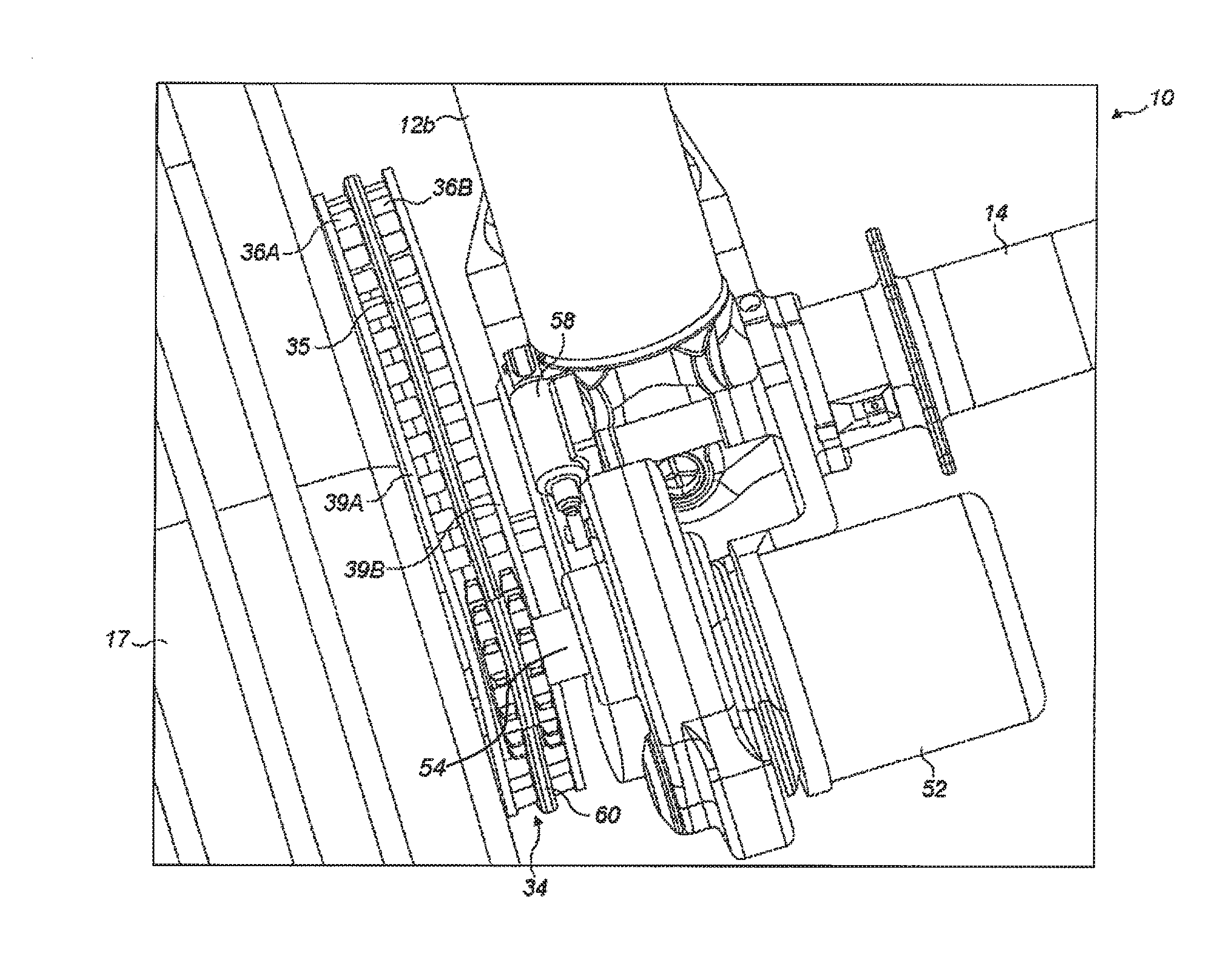
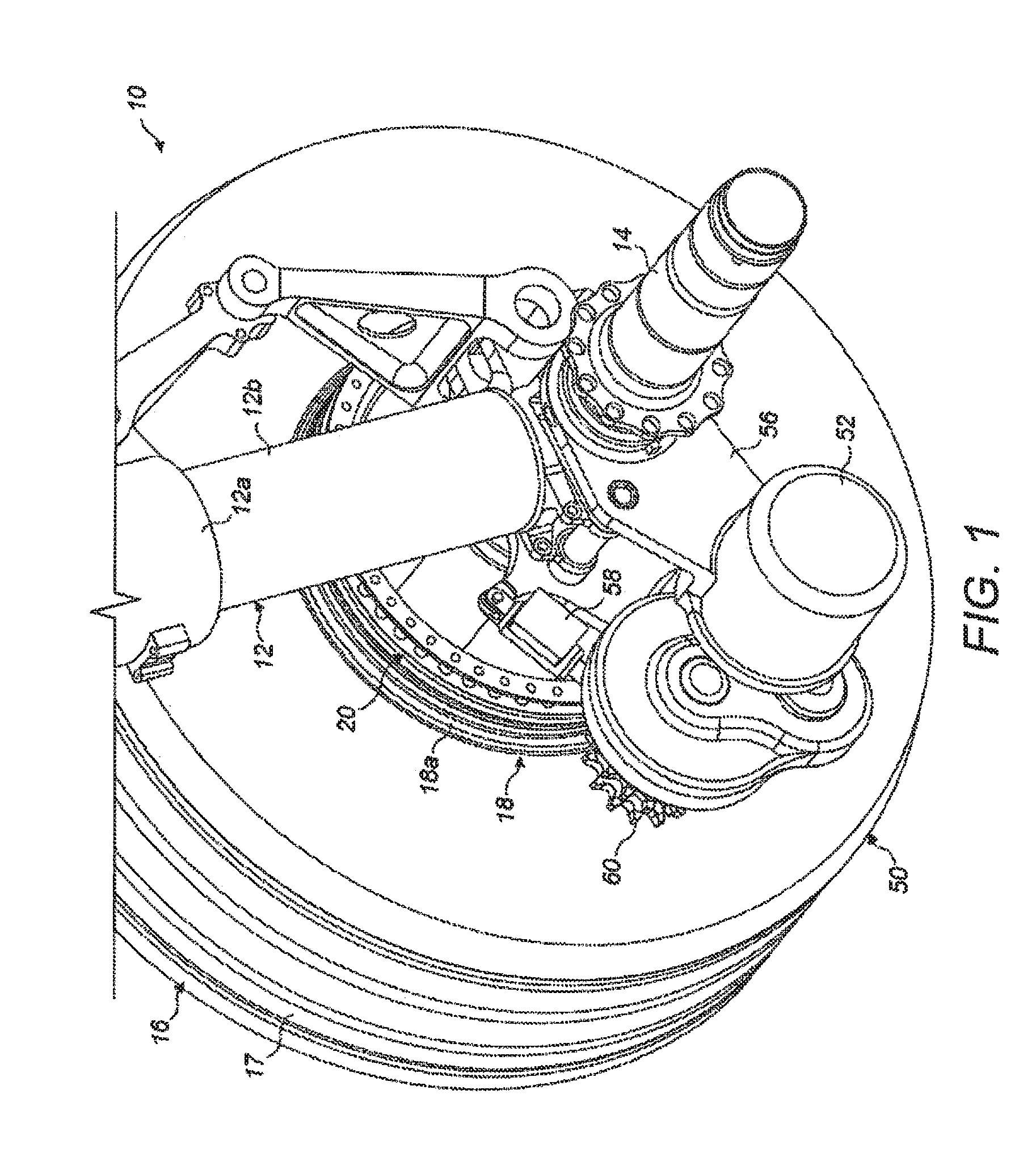
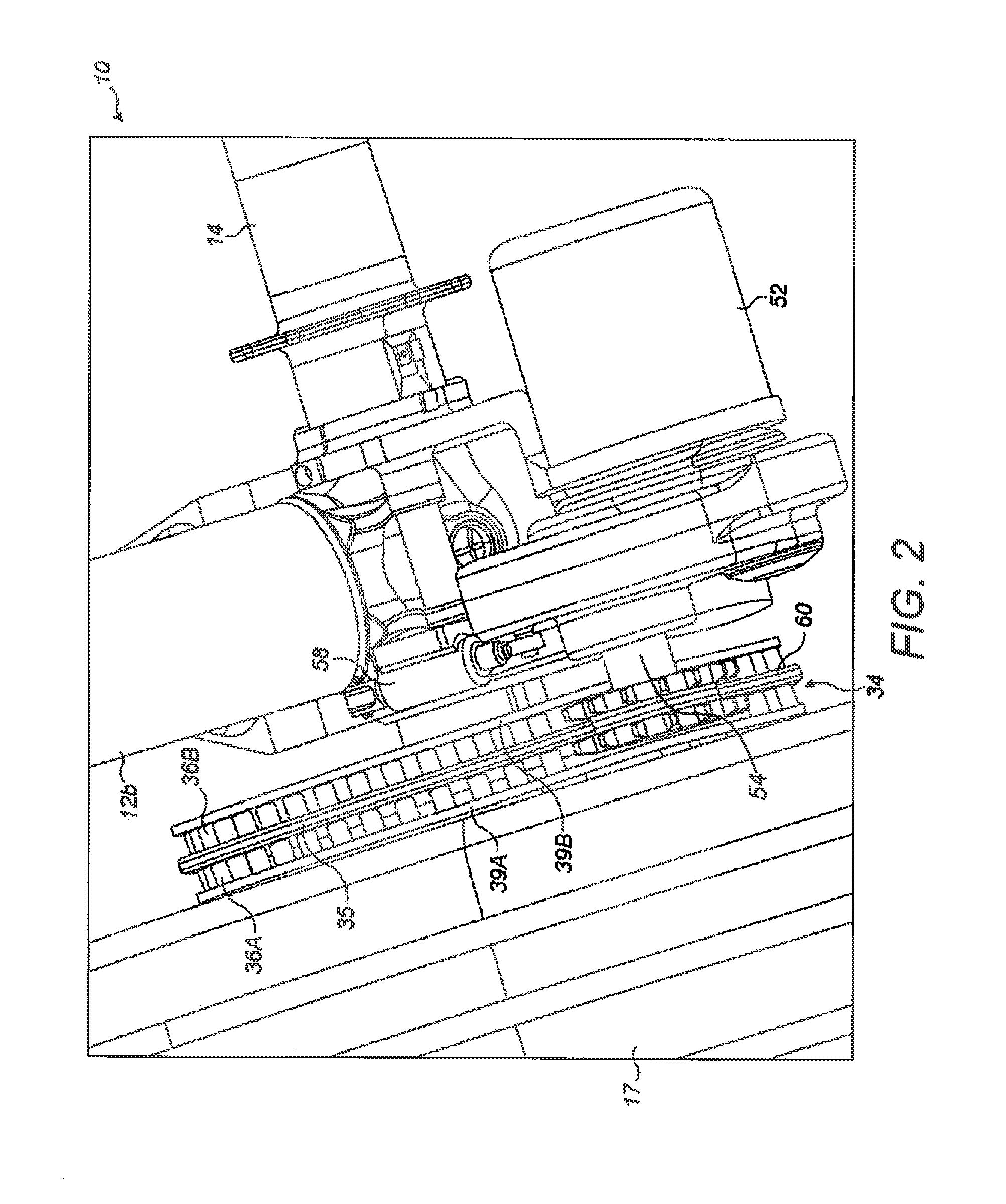
[0037]The illustrated embodiments are shown applied to an aircraft landing gear which has two wheels, but the principles of the embodiments may be applied to landing gear with any number of wheels including only a single wheel. The embodiments are applied to a main landing gear (i.e. a landing gear attached to wing structure or fuselage structure in the region of the wings), since the weight supported by the main landing gear is considered to provide the best traction between the wheels and the ground to enable reliable aircraft ground taxiing. However, the drive system of the present invention may alternatively be applied to a nose landing gear (i.e. a steerable landing gear towards the nose of the aircraft). The main landing gear shown is applicable to a single aisle passenger airliner (approximately 150-200 pax), although it will be appreciated that this invention has wide applicability to a variety of aircraft types and weights, including civil aircraft, military aircraft, heli...


PUM


Abstract

A drive system for rotating a wheel of an aircraft landing gear is disclosed including a motor operable to rotate a drive pinion via a drive path; and a driven gear adapted to be attached to the wheel so as to be capable of rotating the wheel. The drive system has a drive configuration in which the drive pinion is capable of meshing with the driven gear to permit the motor to drive the driven gear via the drive path. The drive path includes a first compensating gear mounted on a common drive shaft with the drive pinion so as to be capable of rotating in tandem with the drive pinion, and a second compensating gear which is meshed with the first compensating gear.

Description

FIELD OF THE INVENTION[0001]The present invention relates to a drive system for rotating one or more wheels of an aircraft landing gear for the purposes of ground taxiing and / or spin-up prior to landing.BACKGROUND OF THE INVENTION[0002]Aircraft are required to ground taxi between locations on airfields. An example is taxiing between a runway and the location (e.g. terminal gate) at which the aircraft's passengers are to board or disembark. Typically, such taxiing is achieved by using the thrust from the aircraft's engines to propel the aircraft forwards so that the landing gear wheels are caused to rotate. Since ground taxi speeds are necessarily relatively low, the engines must be run at a very low power. This means that there is a relatively high fuel consumption as a result of the poor propulsion efficiency at this low power. This leads to an increased level of both atmospheric and noise pollution locally around airports. Moreover, even when the engines are run at low power it is...

Claims


Application Information

Patent Timeline
Patent Type & Authority Applications(United States)
IPC IPC(8): B64C25/40F16H1/20F16H57/00F16H55/10
CPCB64C25/405F16H55/10F16H2057/0012F16H57/0006F16H1/20F16H2035/003Y02T50/80B64C25/34F16H55/30
Inventor DIDEY, ARNAUDWILSON, FRASER
Owner AIRBUS OPERATIONS LTD
Why Eureka
Try Eureka