
Error identifying apparatus

a technology of error identification and apparatus, applied in error detection/correction, instruments, computing, etc., can solve the problems of apparatus not resuming normal operation, unable to guarantee the normal operation of the apparatus, and difficulty in preparing all hardware units necessary for the tes

Inactive Publication Date: 2007-02-22
KONICA MINOLTA BUSINESS TECH INC
View PDF2 Cites 14 Cited by
  • Summary
  • Abstract
  • Description
  • Claims
  • Application Information

AI Technical Summary

Benefits of technology

"The present invention provides an apparatus, error diagnosis system, and error identification procedure that can accurately identify the source of errors in an apparatus. The apparatus can also be put into temporary operation without repairing the failure. The invention includes a plurality of units, each with at least one function executed by software, an error detecting section, a selector section, an obtaining section, an execution section, and a result notifying section. The invention also includes an emulating section and a judgment section to specify the cause of the error. The technical effects of the invention include improved accuracy in identifying errors, improved efficiency in repairing failures, and improved operational flexibility."

Problems solved by technology

In the meantime, in case of developing an application program, it frequently happens that a hardware unit necessary for the operational test of the application program has not been completed yet or that preparation of all hardware units necessary for the test is not easy.
However, because a self-diagnostic program detects the erroneous portion based on a negative phenomenon including, for example, no response from a specified unit or no reaction from a specified sensor, there is no guarantee that the apparatus resumes normal operation after the erroneous portion has been replaced or repaired.
Consequently, there has been a case where the apparatus does not resume normal operation even after replacing the unit that has been determined to be erroneous.
Particularly in a case where the erroneous portion is determined through remote diagnosis and a serviceman brings a new unit into the site for replacement purpose, it would be a waste of time and money if the apparatus cannot be repaired in the end.
In addition, if the erroneous portion determined by a self-diagnostic program is wrong, it has been extremely difficult to identify the real erroneous portion.
Furthermore, once an error occurs, even a temporary operation of the apparatus is not available until the erroneous portion has been repaired.

Method used


Image

  • Error identifying apparatus
  • Error identifying apparatus
  • Error identifying apparatus

Examples


Embodiment Construction

[0030] Preferred embodiment of the invention is described hereunder, using drawing figures.

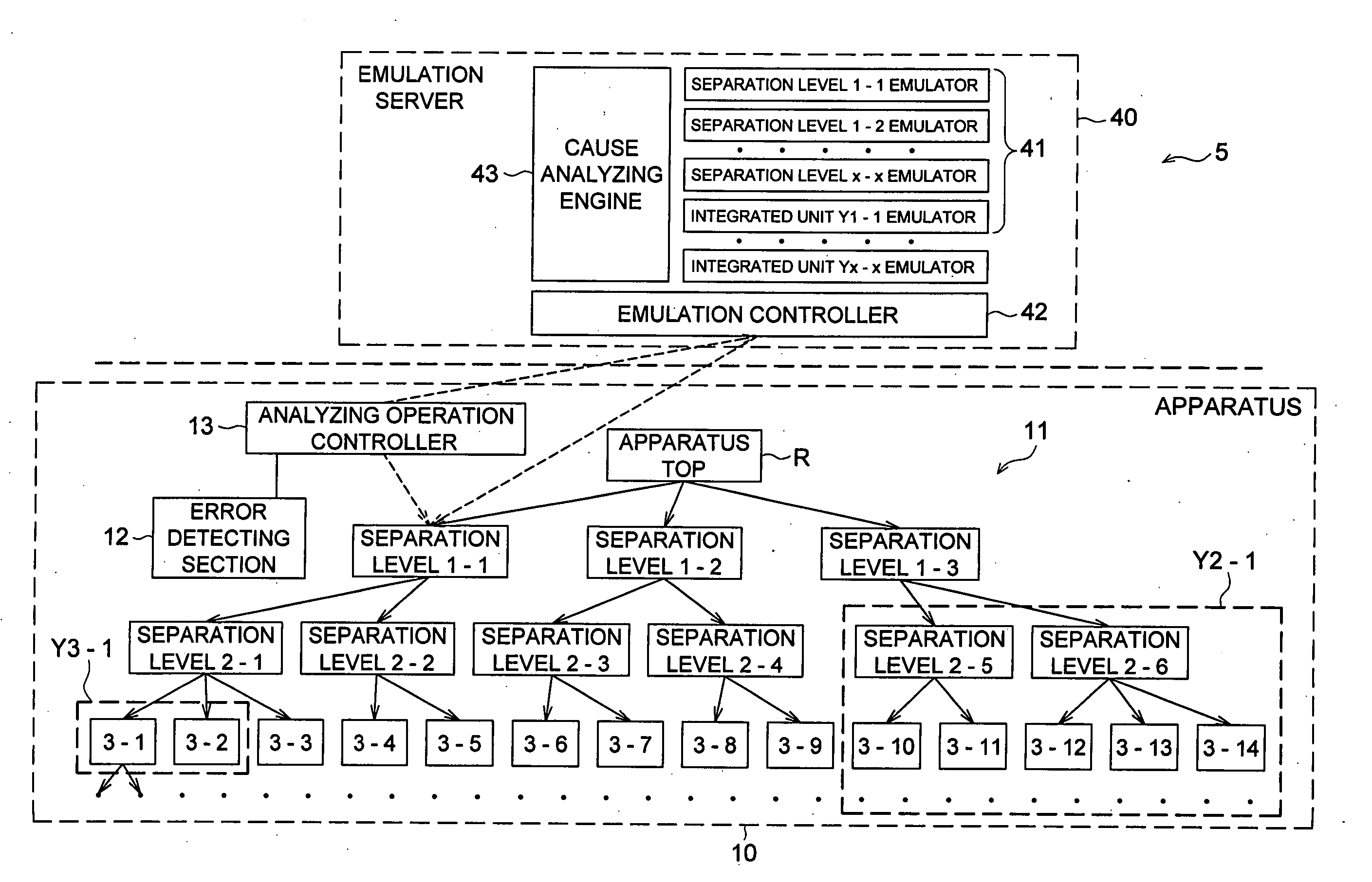
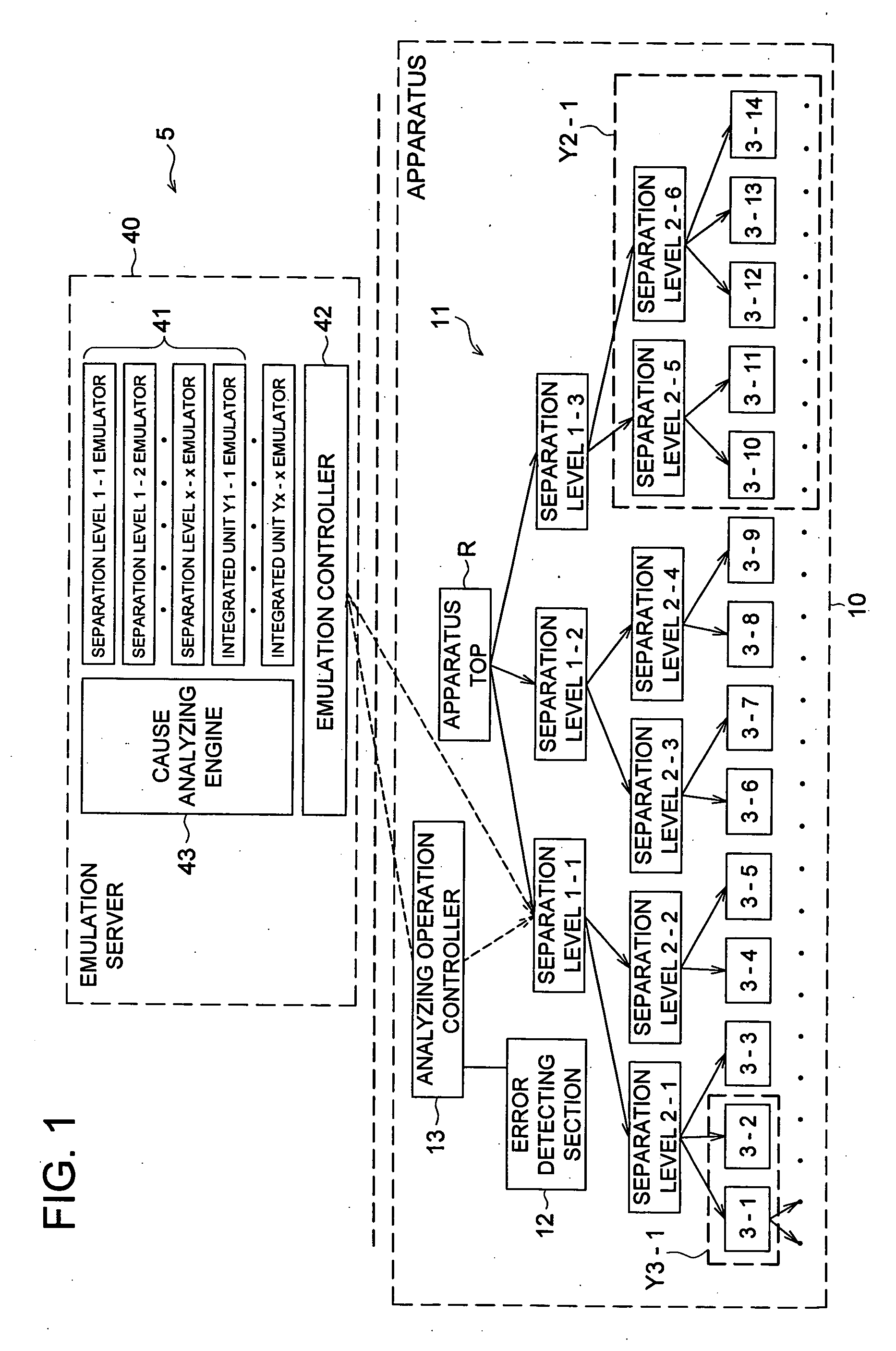
[0031]FIG. 1 shows a brief construction of the error diagnosis system 5 to which the present invention applies. The error diagnosis system 5 comprises an apparatus 10 to be diagnosed and an emulation server 40 as external terminal. The apparatus 10 and emulation server 40 are connected with each other by a communication means such as internet or LAN (local area network).

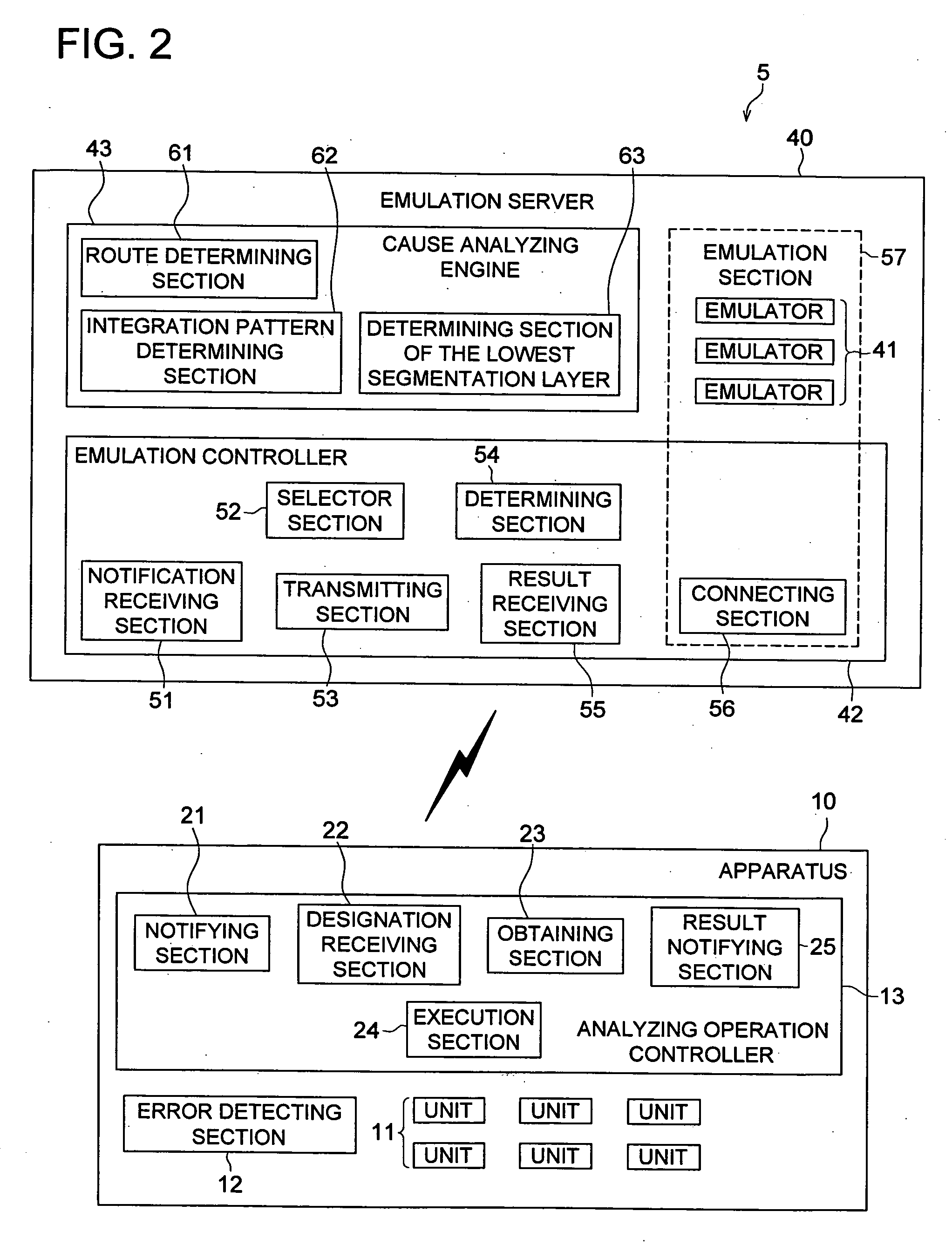
[0032] The apparatus 10 comprises multiple units 11, each of which is a mass of one or more functions that can be substituted by software (hereinafter, sometimes called emulation), error detecting section 12, and analyzing operation controller 13.

[0033] The unit 11 is an assembly of one each or multiple electronic components, electronic boards, and integrated circuit chips (for example ASIC (application specific integrated circuit)) installed on an electronic board. That is, the unit 10 can be regarded to have a hierarchical...


PUM


Abstract

An apparatus, including a plurality of units, each has at least one function which is executed by a software; an error detecting section which detects an error of the apparatus; a selector section which selects at least one of arbitrary unit of the units, when the error is detected by the error detecting section; an obtaining section which obtains from an external device a software function identical to a function of a selected unit by the selector; and an execution section which executes an operation of the apparatus based on the function obtained by the obtaining section.

Description

RELATED APPLICATION [0001] This application is based on Japanese Patent Application No. 2005-237853 filed with Japan Patent Office on Aug. 18, 2005, the entire content of which is hereby incorporated by reference. BACKGROUND [0002] 1. Field of the Invention [0003] The present invention refers to a technique for identifying an error in case the error occurs in an apparatus structured with multiple units. [0004] 2. Description of the Related Art [0005] When a trouble occurs on an apparatus structured with a combination of multiple components and units such as electronic circuit boards, machine units, electronic devices, integrated circuits and sensors, it is a general practice to detect the erroneous portion by a pre-installed self-diagnostic program or determine the type of error from the error code outputted upon the trouble occurrence. [0006] In the meantime, in case of developing an application program, it frequently happens that a hardware unit necessary for the operational test ...

Claims


Application Information

Patent Timeline
Patent Type & Authority Applications(United States)
IPC IPC(8): G06F11/00
CPCG06F11/0733G06F11/0748G06F11/079H04N1/00002H04N1/00037H04N1/0005H04N1/00063H04N1/00084H04N1/00204H04N1/00244H04N1/00973H04N2201/0094
Inventor SUZUKI
Owner KONICA MINOLTA BUSINESS TECH INC
Learn More