

Cap device
a technology of a cap and a rotatable ring, which is applied in the direction of packaging, propulsion parts, vehicle components, etc., can solve the problems of rotatable ring against the mounting groove, rotatable ring no longer rotates smoothly around the mounting groove, etc., and achieves the effect of superior rotatability
- Summary
- Abstract
- Description
- Claims
- Application Information
AI Technical Summary
Benefits of technology
Problems solved by technology
Method used
Image

Examples
first embodiment
A. First Embodiment
[0026] (1) Summary Construction of Cap Device
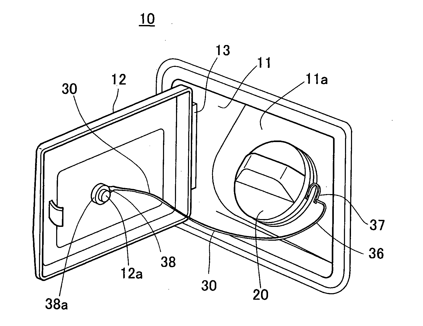
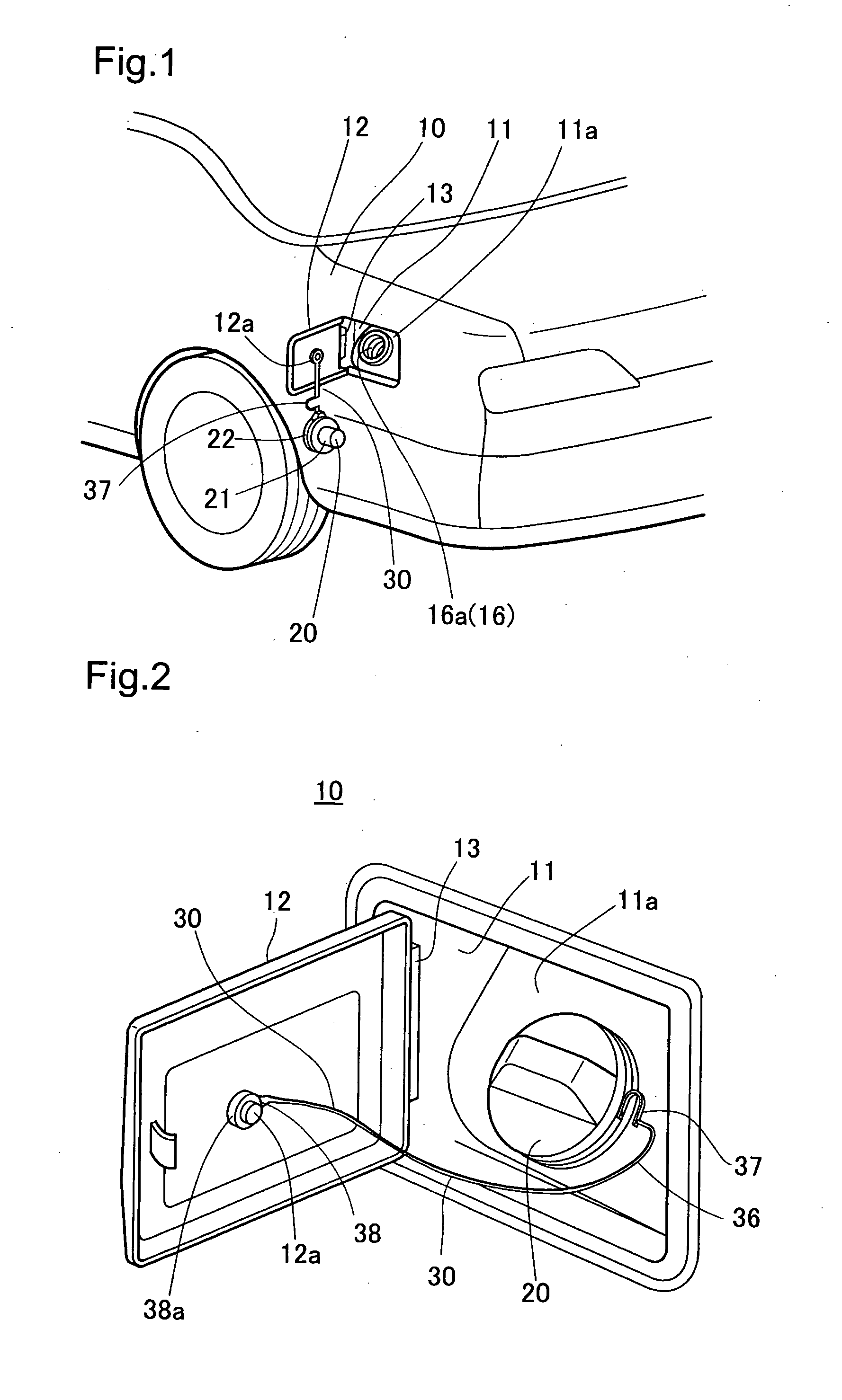
[0027]FIG. 1 is a perspective view showing the rear end of an automobile with a cap device according to a first embodiment of the present invention, and FIG. 2 is a perspective view showing the state in which a fuel supply lid is open. A recession 11 used to supply fuel is formed in the rear portion of the body panel 10 shown in FIG. 1, and the opening of the recession 11 is covered by a fuel supply lid 12. The fuel supply lid 12 is mounted such that it can be opened and closed via a hinge 13. A fuel supply opening 16a of a filler pipe 16 connected to the fuel tank (not shown) is disposed in a bottom wall 11a of the recession 11. The fuel supply opening 16a is opened and closed with a tight seal by the fuel cap 20. The fuel cap 20 is connected to the fuel supply lid 12 by a tether mechanism 30, and loss of the fuel cap 20 is prevented by hanging of the fuel cap 20 during fueling.
[0028] (2) Construction of Fuel Cap 20
[...
second embodiment
B. Second Embodiment
[0045]FIG. 6 shows the main components of a tether mechanism according to a second embodiment. The tether mechanism 30B of the embodiment has a construction in which one element of a rotatable connector 39B is disposed at the second support end 38B of the linking member 36B. The other element of the rotatable connector 39B is disposed at a mounting part 12Ba disposed on the fuel supply lid 12B. An engaging protrusion 12Bb is formed on the mounting part 12Ba. The rotatable connector 39B includes a connector main body 39Ba, and inserting the engaging protrusion 12Bb in an engaging hole 38Ba of the connector main body 39Ba causes the linking member 36B to rotate such that twisting of the linking member 36B is eliminated.
[0046] According to the second embodiment, since the rotatable connector 39B is mounted directly to the mounting part 12Ba of the fuel supply lid 12B, and the rotatable ring and first support end are integrally formed as a single unit, the operation...
third embodiment
C. Third Embodiment
[0047]FIG. 7 is a perspective view showing the fuel cap according to a third embodiment. The rotatable connector 39C according to the embodiment has a construction in which the axis AX, around which the linking member 36C of the tether mechanism 30C rotates, is parallel to the rotational axis of the fuel cap 20. The tether mechanism 30C includes a mounting part 33C that protrudes outward from part of the rotatable ring 32C, and comprises an engaging protrusion 37Cc disposed at a first support end 37C of the linking member main body 36c inserted in an engaging hole 33Cc of the mounting part 33C. With this construction as well, even where the linking member main body 36Ca becomes twisted, this twisting can be eliminated by the linking member main body 36Ca rotating via the rotatable connector 39C.
D. Other Embodiments
[0048] The present invention is not limited to the embodiments described above, and may be implemented in any of various forms within the essential sc...
PUM
 Abstract
Description
Claims
Application Information