Alpha particle shields in chip packaging

a technology of alpha particles and chip packaging, which is applied in the direction of semiconductor devices, electrical equipment, semiconductor/solid-state device details, etc., can solve the problems of large soft errors in the chip during the normal operation of the chip, and achieve the effect of reducing the number of alpha particles

Inactive Publication Date: 2007-03-01
GLOBALFOUNDRIES INC
View PDF5 Cites 17 Cited by
  • Summary
  • Abstract
  • Description
  • Claims
  • Application Information

AI Technical Summary

Benefits of technology

[0010] The present invention provides a structure (and a method for forming the same) that reduces the number of alpha particles that enter the chip.

Problems solved by technology

However, for ceramic substrates, alpha particles (large subatomic fragments consisting of 2 protons and 2 neutrons) continuously emit from the substrate and enter the chip resulting in a large number of soft errors in the chip during the normal operation of the chip.

Method used


Image

  • Alpha particle shields in chip packaging
  • Alpha particle shields in chip packaging
  • Alpha particle shields in chip packaging

Examples


Embodiment Construction

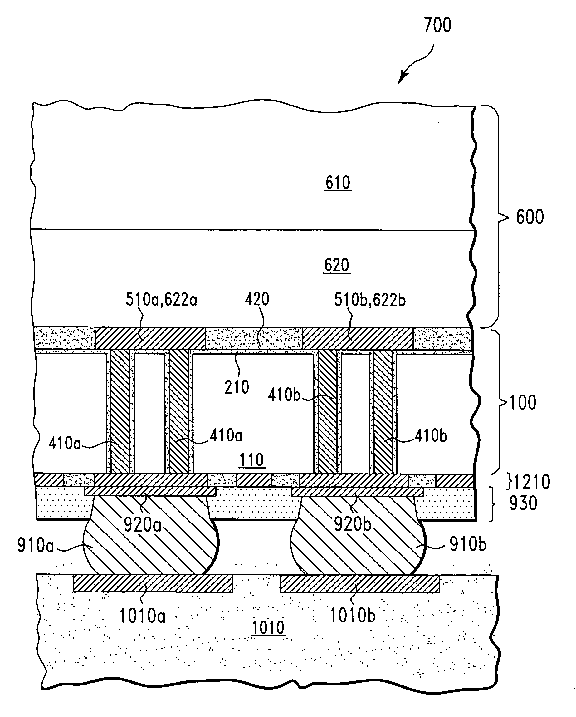
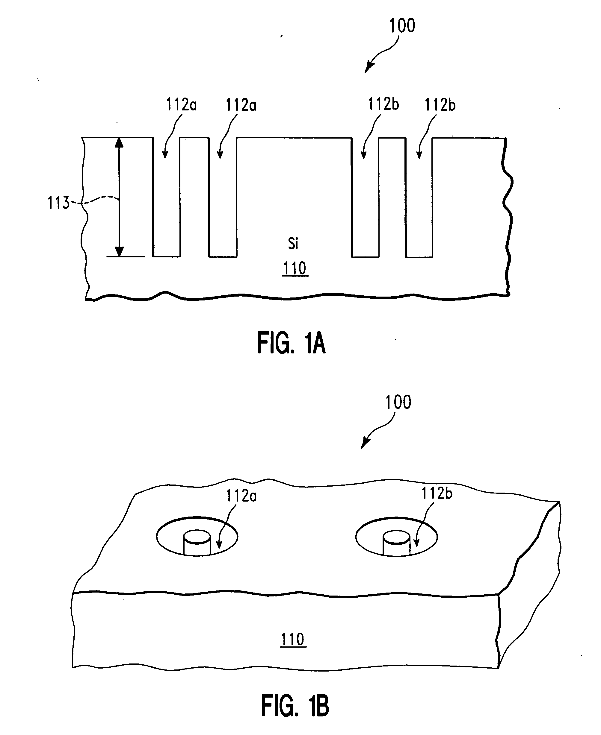
[0012]FIGS. 1-10 show the fabrication process for forming a structure 700 (FIG. 10), in accordance with embodiments of the present invention. More specifically, with reference to FIG. 1A, in one embodiment, the fabrication process starts out with an interposing shield 100 that comprises a semiconductor (e.g., silicon, germanium) layer 110. Next, in one embodiment, annular trenches 112a and 112b are formed in the semiconductor layer 110. Illustratively, the annular trenches 112a and 112b are formed using a photolithographic process. In one embodiment, the annular trenches 112a and 112b have a depth 113 of around 50-70 μm. FIG. 1B shows a perspective view of the interposing shield 100 of FIG. 1A.

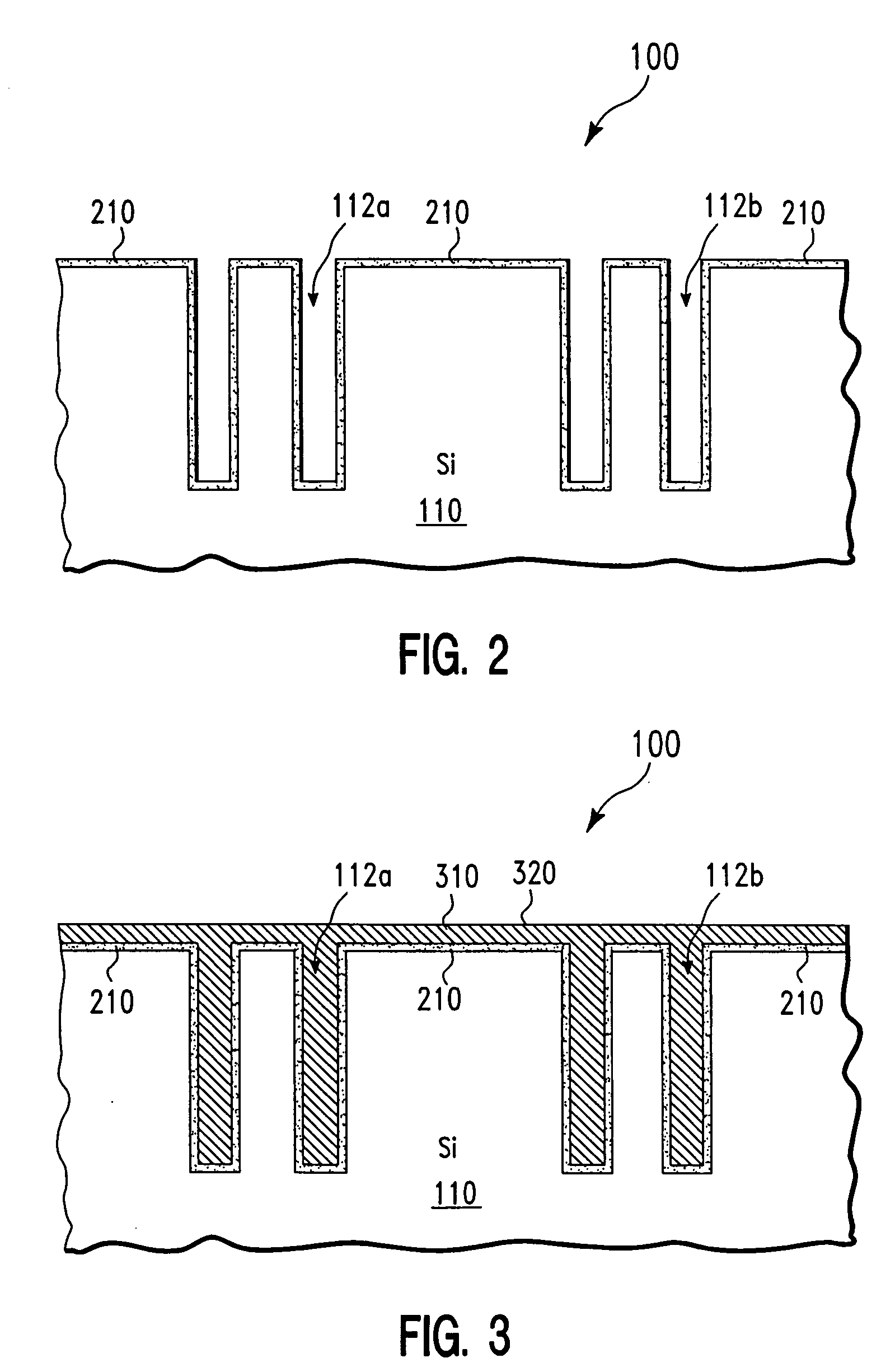
[0013] Next, with reference to FIG. 2, in one embodiment, a dielectric film 210 is formed on exposed-to-ambient silicon surfaces of the interposing shield 100 of FIG. 1A. As a result, the dielectric film 210 forms on, among other places, bottom walls and side walls of the annular trenches 112...


PUM


Abstract

A structure and a method for forming the same. The structure includes an integrated circuit comprising N chip electric pads, wherein N is a positive integer, and wherein the N chip electric pads are electrically connected to a plurality of devices on the integrated circuit. The structure further includes N solder bumps corresponding to the N chip electric pads. A semiconductor interposing shield is sandwiched between the integrated circuit and the N solder bumps. The structure further includes N electric conductors (i) passing through the semiconductor interposing shield and (ii) electrically connecting the N solder bumps to the N chip electric pads.

Description

BACKGROUND OF THE INVENTION [0001] 1. Technical Field [0002] The present invention relates to integrated circuit packaging, and more specifically, to using alpha particle shields in integrated circuit packaging. [0003] 2. Related Art [0004] In flip-chip technologies, solder bumps are typically formed on top of a semiconductor chip (i.e., integrated circuit IC). Each solder bump is formed directly on a bond pad of the chip. Then the chip is flipped face down and then aligned to a package / substrate so that the solder bumps are bonded directly, simultaneously, and one-to-one to the pads of the package / substrate (called package / substrate pads). However, for ceramic substrates, alpha particles (large subatomic fragments consisting of 2 protons and 2 neutrons) continuously emit from the substrate and enter the chip resulting in a large number of soft errors in the chip during the normal operation of the chip. Alpha particles are also generated from 210Pb contained in the solder bumps. [00...

Claims


Application Information

Patent Timeline
Patent Type & Authority Applications(United States)
IPC IPC(8): H01L23/48
CPCH01L2224/83801H01L2924/01074H01L23/556H01L2224/73204H01L2924/01033H01L2224/29111H01L2924/01005H01L2924/0105H01L2224/81801H01L2924/19043H01L24/81H01L2924/14H01L2924/014H01L24/29H01L2924/01078H01L2924/01072H01L2924/04953H01L2924/19041H01L2924/15787H01L2924/01013H01L2924/15311H01L2924/3025H01L2224/16H01L24/83H01L2924/01082H01L2924/0132H01L2924/01029H01L2924/01073H01L2924/01006H01L2224/13111H01L2924/00014H01L21/304H01L21/481H01L24/11H01L2224/16113H01L2224/16225H01L2224/16227H01L2924/01014H01L2924/2064
Inventor ANDRY, PAULCABRAL, CYRILRODBELL, KENNETHWISNIEFF, ROBERT
Owner GLOBALFOUNDRIES INC
Why Eureka
Try Eureka