Aircraft flat panel display system with improved information availability

a flat panel display and information availability technology, applied in the direction of navigation instruments, simultaneous indication of multiple variables, instruments, etc., can solve the problem of video graphics processors not rendering correct images, etc., and achieve the effect of simple representation, low fidelity, and simple line representation

Active Publication Date: 2007-03-01
INNOVATIVE SOLUTIONS & SUPPORT
View PDF11 Cites 98 Cited by
  • Summary
  • Abstract
  • Description
  • Claims
  • Application Information

AI Technical Summary

Benefits of technology

The patent text describes a system where a primary video graphics processor provides high fidelity video graphics information and a secondary video graphics processor provides low fidelity video graphics information. This allows for different potential failure threads for the primary and secondary processors, as they may have different system architectures, brands, or types. The technical effect of this is improved reliability and redundancy in the video imaging system, ensuring that the system can still operate even if one of the processors fails.

Problems solved by technology

The technical problem addressed in this patent text is the need for an improved graphics display system for use in aircraft that can accommodate readily-upgradeable graphics display components and subsystems without adversely affecting existing FAA certification or requiring extensive recertification of the instrumentation display system. The solution disclosed in the patent text uses a comparator processor and a pixel verification map to independently check the accuracy of the generated images without the need for additional hardware or software. However, the system still requires extensive testing and documentation to obtain FAA recertification.

Method used


Image

  • Aircraft flat panel display system with improved information availability
  • Aircraft flat panel display system with improved information availability
  • Aircraft flat panel display system with improved information availability

Examples


Embodiment Construction

)

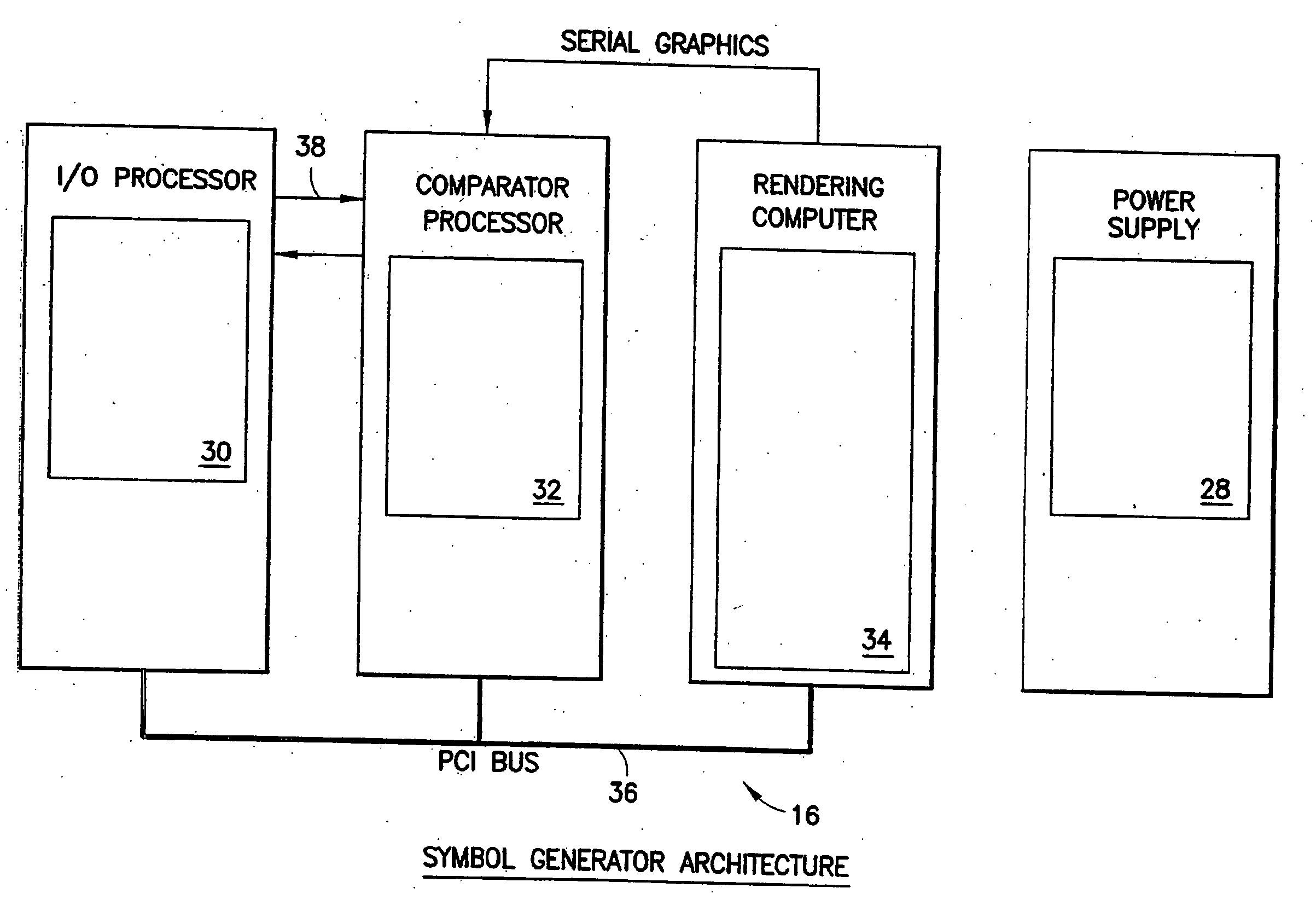
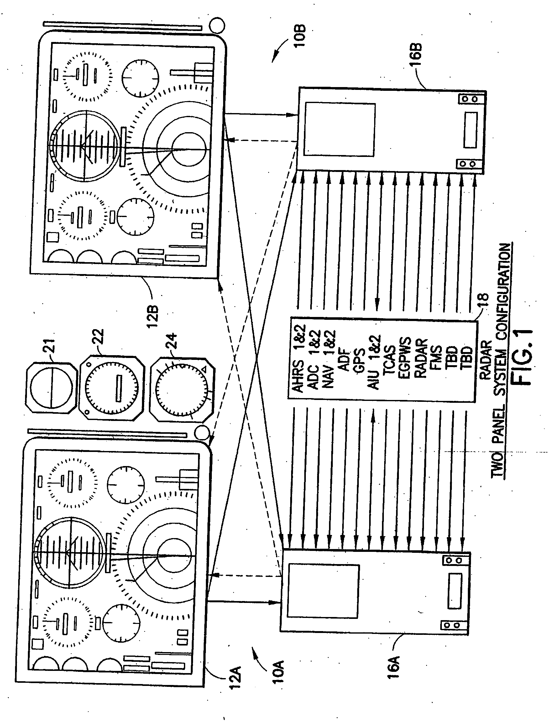
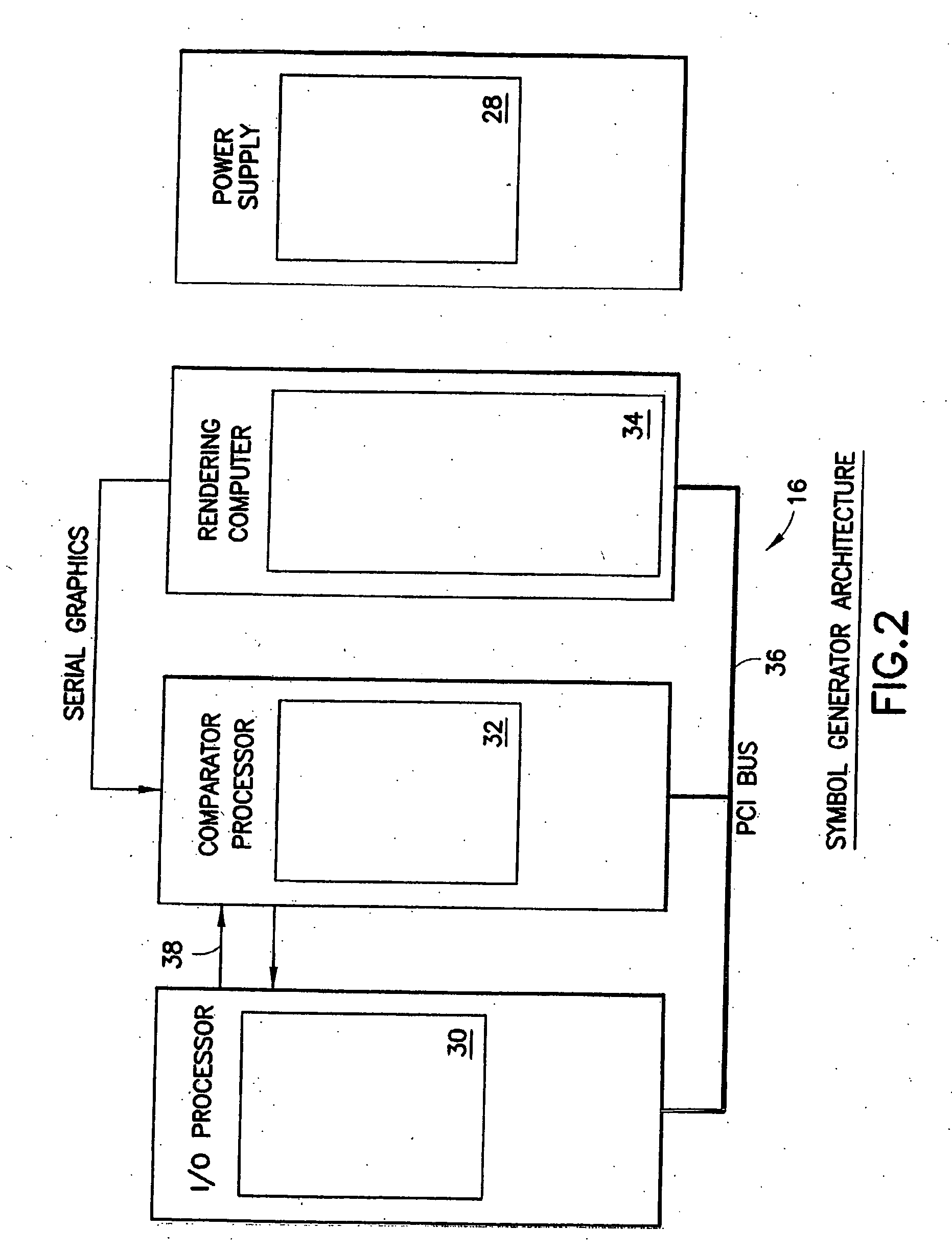
[0029]FIG. 1 depicts an implementation of an aircraft flight panel dual display system constructed in accordance with the system of U.S. Pat. No. 6,693,558 (“the '558 patent”). The present invention is an improvement on the '558 system as well as an improvement on the system described in our commonly owned copending U.S. patent application entitled “Improved Aircraft Flat Panel Display System With Graphical Image Integrity” of which this application is a continuation-in-part, and which is described below with reference to FIGS. 7-10. The system of the present invention will be further described herein with additional reference to FIGS. 11-13.

[0030] However, in order to understand the improved system of FIGS. 11-13 better, the '558 system shall be described first with respect to FIGS. 1-6 and, thereafter, the system of FIGS. 7-10 will be described before the improved system of the present invention is described.

[0031] Dual control stations, e.g. a pilot station and a co-pilot stat...


PUM


Abstract

An improved aircraft instrument flight display system employs primary and secondary video graphics processors for generating graphics video imaging information. Both the primary and secondary video graphics processors have associated potential failure threads and are preferably chosen to have different potential failure threads so that the same failure problem will not have a tendency to occur in both of the video graphics processors. The primary video graphics processor generates a graphical display of the aircraft flight information for use by the flight crew in operating the aircraft. The system also includes a video switch for switching between the primary and secondary video graphics processors under control of the integrity checking processor based on the integrity of the graphical display provided by the primary video graphics processor. The switch switches its output to the secondary video graphics processor when the integrity checking processor detects a mismatch condition for the primary video graphics processor in order to maintain critical display data availability when a mismatch has been detected with respect to the primary video graphics processor. The video imaging information provided by the secondary video graphics processor can be a subset of the video imaging information provided by the primary video graphics processor or it can be the same. The integrity checking function may be accomplished by storing a complex checksum, such as a CRC, for a predefined image of each graphics image capable of being rendered as a baseline, and calculating an image checksum for the rendered image and comparing it against the stored complex checksum corresponding to the image for determining any deviations from the baseline.

Description


Claims


Application Information

Patent Timeline
Owner INNOVATIVE SOLUTIONS & SUPPORT
Why Eureka
Try Eureka