Structure to prevent deformation of magnetic disk device housing

Inactive Publication Date: 2007-03-01
WESTERN DIGITAL TECH INC
View PDF9 Cites 4 Cited by
  • Summary
  • Abstract
  • Description
  • Claims
  • Application Information

AI Technical Summary

Benefits of technology

[0021] Because the slip mechanism reducing the slip friction resistance is provided respectively in the contact portion between the flat part of the base and the top cover and the contact portion between the head part of the screw and the top cover, even if the bimetal effect occurs, it is possible to cause the base and the top cover to slip in the plane direction of the base concerned. As this slip mechanism, one may apply a lubricant to the contact portion, or dispense a mirror face working to the contact portion. Further, in the case where, in the portion in which the flat part and the top cover contact, the friction coefficient in the tightening part of the screw becomes lower than the friction coefficient of other portion, even

Problems solved by technology

However, since this positional deviation changes by the use environment temperature, it has to be corrected each time the temperature changes.
However, the rubber member becomes hard if tightened by the fixation screw, so that a problem arises when its elastic function decreases.
However, since the base board and the cover member are not fixed so as not to move, it is unsuitable for a fixation structure of th

Method used


Image

  • Structure to prevent deformation of magnetic disk device housing
  • Structure to prevent deformation of magnetic disk device housing
  • Structure to prevent deformation of magnetic disk device housing

Examples


Embodiment Construction

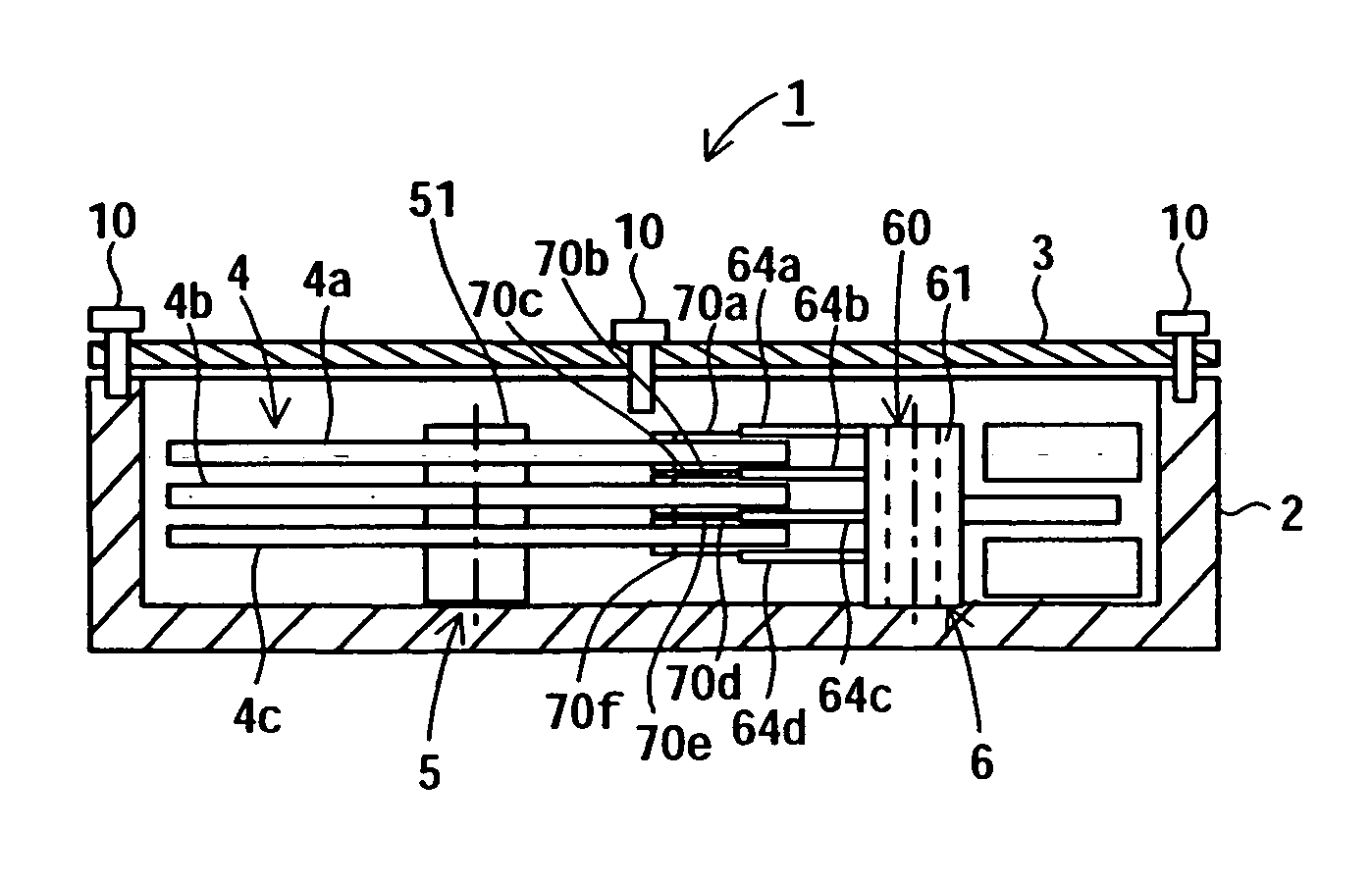
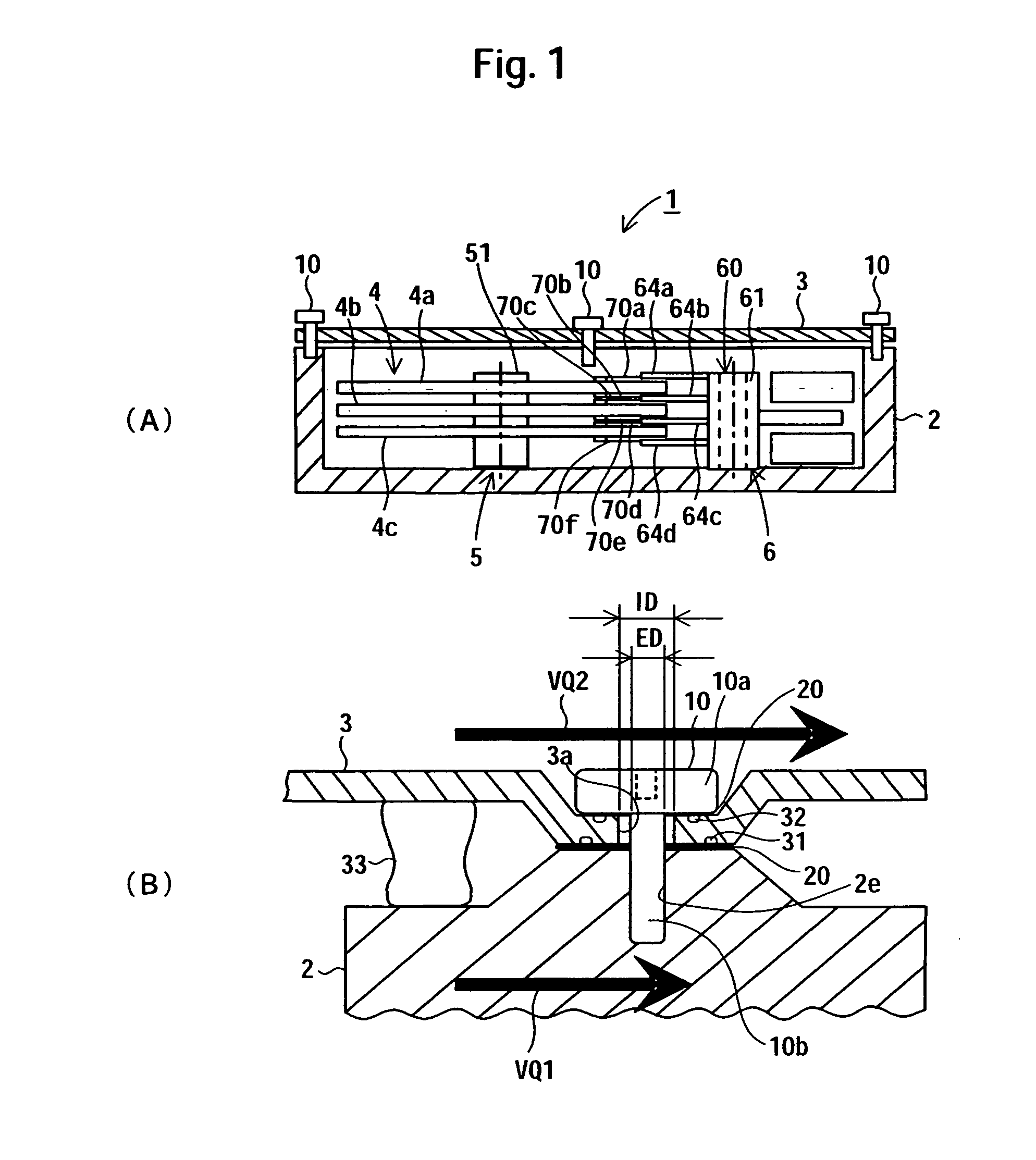
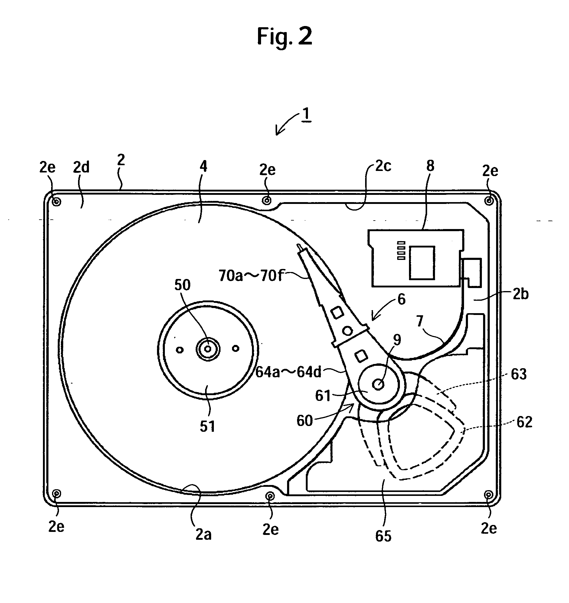
[0027] An exemplary embodiment of the present invention is described by referring to the drawings. Throughout the present specification, the same reference numeral is used to refer to the same element. FIG. 1 is a view showing an exemplary embodiment of the invention, in which a base and a top cover have been fixed by screws, wherein (A) is a whole sectional view, and (B) an enlarged sectional view. FIG. 2 is a plan view showing a schematic constitution of a magnetic disk unit in the present invention.

[0028] As shown in FIG. 1 and FIG. 2, a magnetic disk unit 1 forms a sealed space of clean air, which has been formed by a base 2 and a top cover 3 over an upper part of the base 2, and accommodates in its interior space a magnetic disk 4, a spindle motor 5 that is a head drive mechanism, an HSA 6, and the like. Further, into the base 2, there are incorporated a flexible cable 7 and an external connection terminal 8 mounted to the flexible cable 7. To the external connection terminal ...


PUM


Abstract

Embodiments of the invention provide a magnetic disk unit in which there has been adopted a structure fixing a base and a top plate and preventing a deformation by a bimetal effect. In one embodiment, the magnetic disk unit includes a magnetic disk; a head drive mechanism in which is mounted a head accessing the magnetic disk; a base accommodating the magnetic disk and the head drive mechanism, and possessing a flat part, in which a threaded hole has been formed, in a circumference of an opening edge; and a top cover which is formed by a material whose thermal expansion coefficient differs from that of the base, in which there is provided an escape hole, for a screw, position-aligned to the threaded hole of the flat part, and which is attached to the base by the screw penetrating through the threaded hole and the escape hole for the screw. A slip mechanism for reducing a slip friction resistance is provided respectively in a contact portion between the flat part and the top cover, and a contact portion between a head part of the screw and the top cover.

Description

CROSS-REFERENCES TO RELATED APPLICATIONS [0001] This application claims priority from Japanese Patent Application No. JP2005-245817, filed Aug. 26, 2005, the entire disclosure of which is incorporated herein by reference. BACKGROUND OF THE INVENTION [0002] The present invention relates to an attachment structure of a base and a top cover in a storage device such as magnetic disk unit and magneto-optical unit, and more particularly relates to an attachment structure which prevents deformation of the base or the top cover due to a temperature change. [0003] In the magnetic disk unit, a mechanical apparatus is constituted as a head disk assembly (hereafter, mentioned as HDA in the specification). This HDA is constituted by the base, a magnetic disk having been accommodated in the base, a head support mechanism, a spindle motor and electronic components etc., and by the top cover which forms a sealed structure by being joined to the base in order to form an enclosure to provide a clean ...

Claims


Application Information

Patent Timeline
IPC IPC(8): G11B15/48
CPCG11B33/1433
Inventor SHIGENAGA, HIROAKIYONEKAWA, SUNAOIWAKURA, MASAOMIYATAKE, MASAMI
Owner WESTERN DIGITAL TECH INC
Why Eureka
Try Eureka