Multi-Microphone System

a microphone and microphone technology, applied in the field of mems microphones, can solve the problems of diaphragm bowing, signal that is too small to be measured, signal that can be relatively easily corrupted by noise,

Active Publication Date: 2007-03-01
INVENSENSE
View PDF92 Cites 153 Cited by
  • Summary
  • Abstract
  • Description
  • Claims
  • Application Information

AI Technical Summary

Benefits of technology

[0005] In accordance with one embodiment of the invention, a microphone system implements multiple microphones on a single base. To that end, the microphone system has a base, and a plurality of substantially independently

Problems solved by technology

If too small, it may produce a signal that can be relatively easily corrupted by noise.
In addition, a small diaphragm also may produce a signal that is too small to be measured.
Conversely, if too large (but hav

Method used


Image

  • Multi-Microphone System
  • Multi-Microphone System
  • Multi-Microphone System

Examples


Embodiment Construction

[0020] In illustrative embodiments, a microphone system has a plurality of microphones coupled to, and essentially integrated with, the same base. Accordingly, compared to microphones having a single diaphragm of similar area and materials, the sensitivity and signal to noise ratio of such a system should be improved while maintaining a relatively thin profile. Details of illustrative embodiments are discussed below.

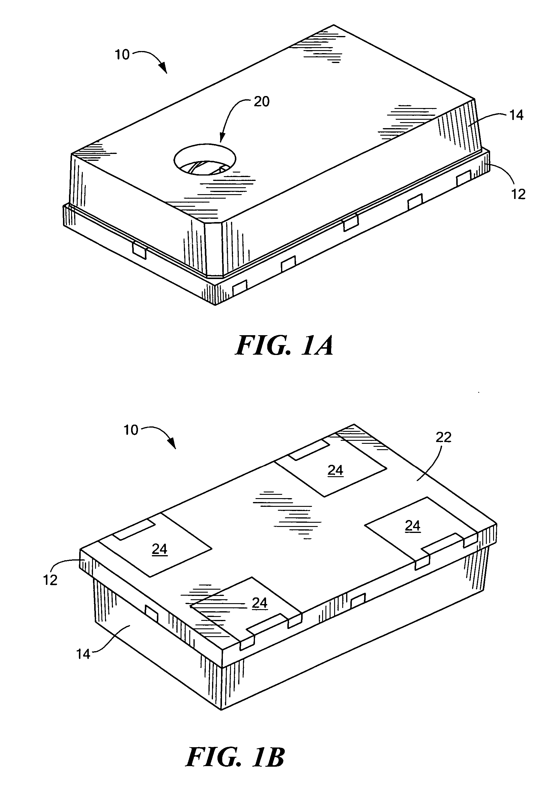
[0021]FIG. 1A schematically shows a top, perspective view of a packaged microphone 10 that may be configured in accordance with illustrative embodiments of the invention. In a corresponding manner, FIG. 1B schematically, shows a bottom, perspective view of the same packaged microphone 10.

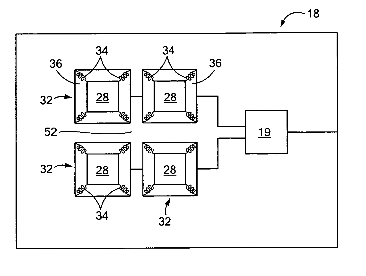
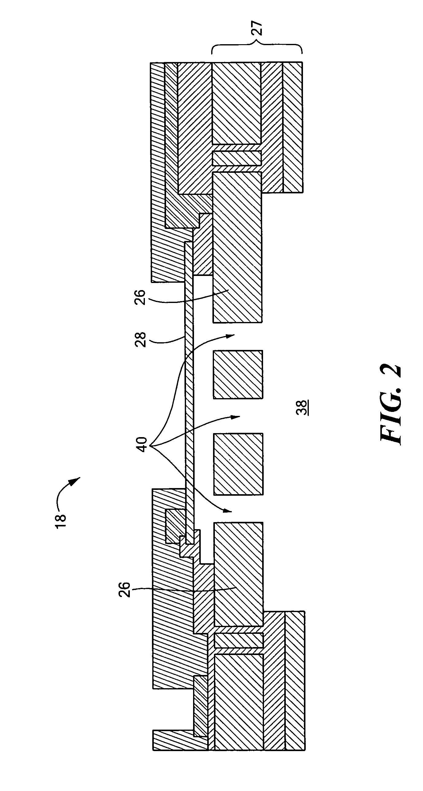
[0022] The packaged microphone 10 shown in those figures has a package base 12 that, together with a corresponding lid 14, forms an interior chamber 16 containing a microphone chip 18 (discussed below, see FIG. 2 and others) and, if desired, separate microphone circuitry 19 (shown sche...


PUM


Abstract

A microphone system implements multiple microphones on a single base. To that end, the microphone system has a base, and a plurality of substantially independently movable diaphragms secured to the base. Each of the plurality of diaphragms forms a variable capacitance with the base and thus, each diaphragm effectively forms a generally independent, separate microphone with the base.

Description

PRIORITY [0001] This patent application claims priority from provisional U.S. patent application No. 60 / 710,624, filed Aug. 23, 2005 entitled, “MULTI MICROPHONE SYSTEM,” and naming Jason Weigold and Kieran Harney as inventors, the disclosure of which is incorporated herein, in its entirety, by reference.FIELD OF THE INVENTION [0002] The invention generally relates to MEMS microphones and, more particularly, the invention relates to improving the performance of MEMS microphones. BACKGROUND OF THE INVENTION [0003] Condenser MEMS microphones typically have a diaphragm that forms a capacitor with an underlying backplate. Receipt of an audible signal causes the diaphragm to vibrate to form a variable capacitance signal representing the audible signal. It is this variable capacitance signal that can be amplified, recorded, or otherwise transmitted to another electronic device. [0004] The area of the diaphragm has a direct relation to the total capacitance of the microphone. If too small, ...

Claims


Application Information

Patent Timeline
IPC IPC(8): H04R25/00
CPCH04R1/406H04R1/083H04R19/04H04R19/005
Inventor WEIGOLD, JASON W.HARNEY, KIERAN P.
Owner INVENSENSE
Why Eureka
Try Eureka