Debris-filtering technique for gas turbine engine component air cooling system

a technology for gas turbine engines and air cooling systems, which is applied in the direction of machines/engines, liquid fuel engines, separation processes, etc., can solve the problems of clogging one the combined area of the plurality of openings exceeding the area of metering locations,

Inactive Publication Date: 2007-03-01
UNITED TECH CORP
View PDF25 Cites 45 Cited by
  • Summary
  • Abstract
  • Description
  • Claims
  • Application Information

AI Technical Summary

Benefits of technology

[0012] By providing the relatively small openings upstream of the metering location, the present invention ensures that impurities are filtered before reaching the metering location.

Problems solved by technology

However, the combined area of the plurality of openings exceeds the area of metering location.
Thus, any one of the openings may become clogged by impurities, and yet adequate air will still be delivered.
Again, any one of the plurality of openings may become clogged by impurities.

Method used


Image

  • Debris-filtering technique for gas turbine engine component air cooling system
  • Debris-filtering technique for gas turbine engine component air cooling system
  • Debris-filtering technique for gas turbine engine component air cooling system

Examples


Embodiment Construction

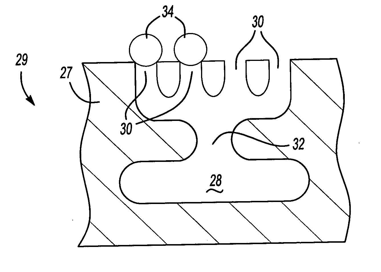
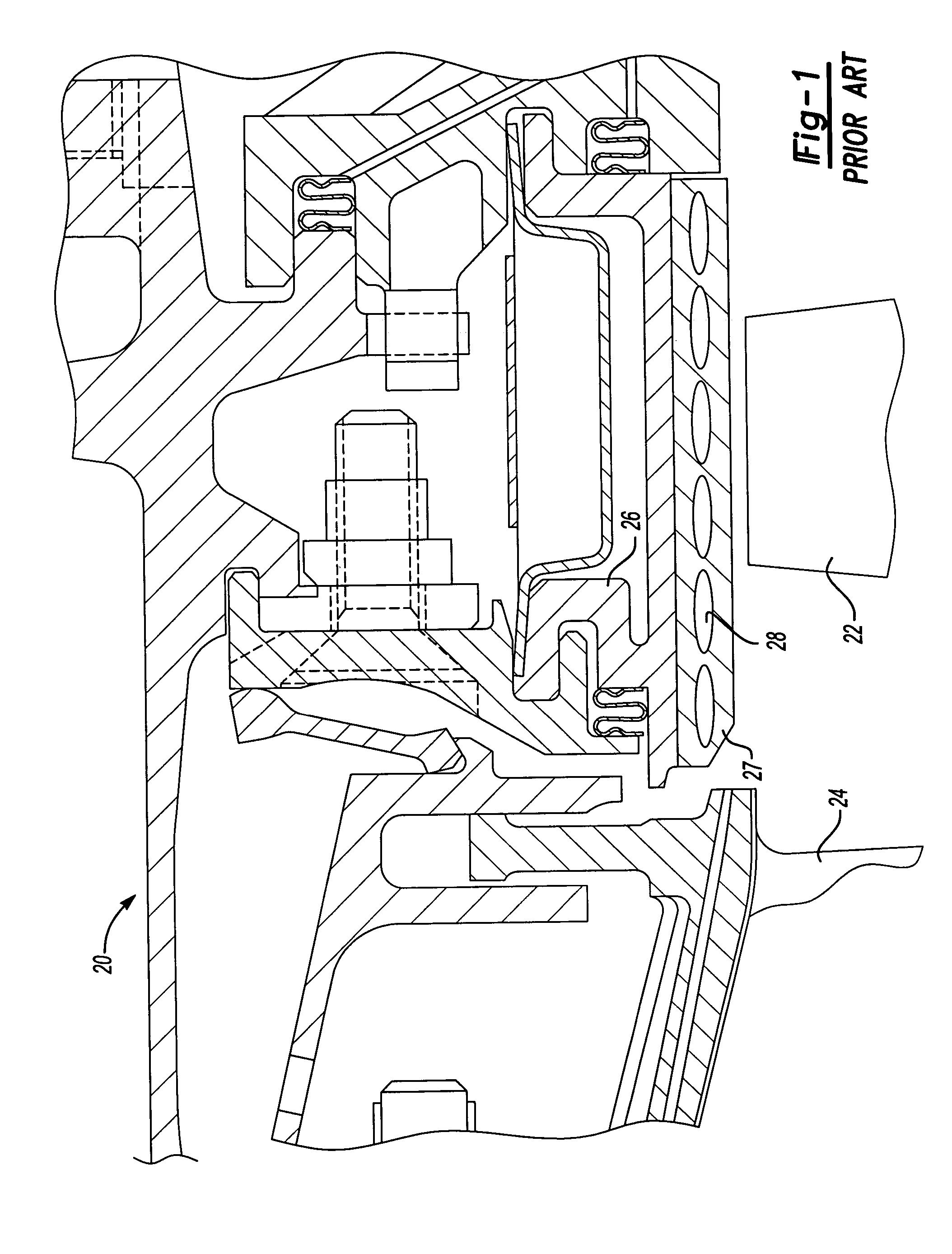
[0025]FIG. 1 shows a portion of a gas turbine engine 20 incorporating a rotating turbine blade 22 and a stationary vane 24. As is known, a blade outer air seal 26 is positioned radially outwardly of the turbine blade 22. A housing 27 of the blade outer air seal 26 includes a number of channels 28. The channels are shown somewhat schematically, and may be as known in the prior art. The present invention is directed to providing air flow to the cooling channels such that impurities are filtered before reaching any relatively small location along the channel.

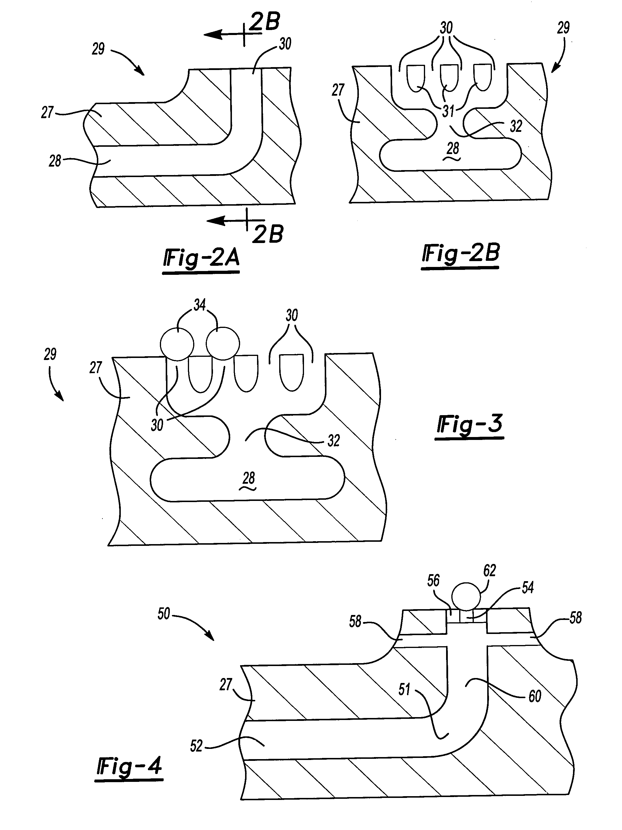
[0026]FIG. 2A shows a first embodiment 29. The housing 27 that includes the cooling air passage 28 is provided with an opening 30. This embodiment is particularly useful when the cooling air passages are microcircuit cooling passages. Such microcircuit cooling passages are known, and are formed to an extremely small passage diameter. Thus, these passages are especially prone to being clogged by impurities.

[0027] As shown in FIG. ...


PUM

PropertyMeasurementUnit
areaaaaaaaaaaa
cross-sectional areaaaaaaaaaaa
thermal stressesaaaaaaaaaa

Abstract

Air cooling passages for a gas turbine engine component, and in particular, a blade outer air seal, are provided with a filtering technique to filter impurities before they can reach a metering location. The air filtering techniques include the provision of a plurality of openings which each have a small cross-sectional area when compared to the cross-sectional area of the metering location. These small openings will filter out impurities before they reach the metering location. The metering location has a cross-sectional area that is greater than the cross-sectional area of any one of the openings, however, the total cross-sectional area of the plurality of openings exceeds the cross-sectional area of the metering location such that adequate air is supplied even if several of the openings are clogged.

Description

BACKGROUND OF THE INVENTION [0001] This application relates to a method of filtering impurities from air entering a gas turbine component air cooling system, such that cooling passages are not clogged. [0002] Gas turbine engines are provided with a number of functional sections, including a fan section, a compressor section, a combustion section, and a turbine section. Within each of these sections, there are a number of components that are exposed to high heat, and resultant thermal stresses, etc. Thus, it is well known to provide cooling air to internal cooling channels for these components. [0003] The cooling channels often are rather small. As an example, one recently developed type of cooling channel is a so-called microcircuit cooling system. In a microcircuit cooling system, very tiny cooling channels are formed in the turbine components. [0004] For several reasons, the air flow within a gas turbine engine may include dirt or other impurities. As one example, for jet engines ...

Claims


Application Information

Patent Timeline
Patent Type & Authority Applications(United States)
IPC IPC(8): F03B11/00
CPCB01D46/40F01D11/005Y02T50/675F05D2260/607F01D11/08Y02T50/60
Inventor VAN SUETENDAEL, ARTHUR J. IVROMANOV, DMITRIY
Owner UNITED TECH CORP
Why Eureka
Try Eureka