Electrical connection arrangement

a technology of electrical connection and arrangement, applied in the direction of multiple conductor connectors, contact members penetrating/cutting insulation/cable strands, transformer/coil connectors, etc., can solve the problems of mechanical damage on the first contact device, danger of electrical shock, etc., and achieve the effect of improving and simplifying the connection properties

Inactive Publication Date: 2007-03-01
PHOENIX CONTACT GMBH & CO KG
View PDF10 Cites 6 Cited by
  • Summary
  • Abstract
  • Description
  • Claims
  • Application Information

AI Technical Summary

Benefits of technology

[0007] Therefore, a primary object of the present invention is to provide an electrical connection arrangement with improved and simplified connection properties.
[0009] The electrical connection arrangement in accordance with the invention is advantageous in many respects. Because the contact body is located in the top part of the connection arrangement, a contact point is omitted relative to the connection arrangements known from the prior art, specifically the contact point between the contact bodies located in the bottom part and in the top part. Furthermore, the contact-making process of the device-side cable becomes much simpler and safer since contact between the contact body and the device-side cable is only produced in the joined position of the bottom part and the top part. Thus, there is neither the danger of mechanical damage on the first contact device which produces the connection, nor the danger of an electrical shock by touching the first contact device which may be energized.
[0010] The connection arrangement in accordance with the invention can be farther improved with respect to its applicability by the first contact device of the contact body being made as an insulation piercing contact. This has the advantage that the device-side cable can be worked completely insulated and after contact-making by the insulation piercing contacts a safe and vibration-proof electrical connection is produced.
[0011] According to other advantageous embodiments of the invention, the second contact device is executed as a spring terminal or screw-type terminal for contact-making of the connection-side cable. In this way, the electrical and mechanical connection of the connection-side cable to the contact body can be easily detached again almost as often as desired, a safe electrical connection still being ensured.
[0016] In another advantageous configuration of the electrical connection arrangement, the top part can be locked to the bottom part or each top part segment can be locked to the bottom part in the joined position, especially by catch elements which are assigned to the top part and the top part segment and which in the joined position can be caused to engage the corresponding catch element recesses in the bottom part of the connection arrangement. Especially preferably the catch element and the catch element recess are made such that when the bottom part and the top part or the bottom part and the top part segment are joined, they act exactly like a guide, and thus, ensure exact positioning of the first contact device relative to the device-side cable which is fixed in the fastening means of the bottom part and as a result ensure reliable contact-making.

Problems solved by technology

Thus, there is neither the danger of mechanical damage on the first contact device which produces the connection, nor the danger of an electrical shock by touching the first contact device which may be energized.

Method used


Image

  • Electrical connection arrangement
  • Electrical connection arrangement
  • Electrical connection arrangement

Examples


Embodiment Construction

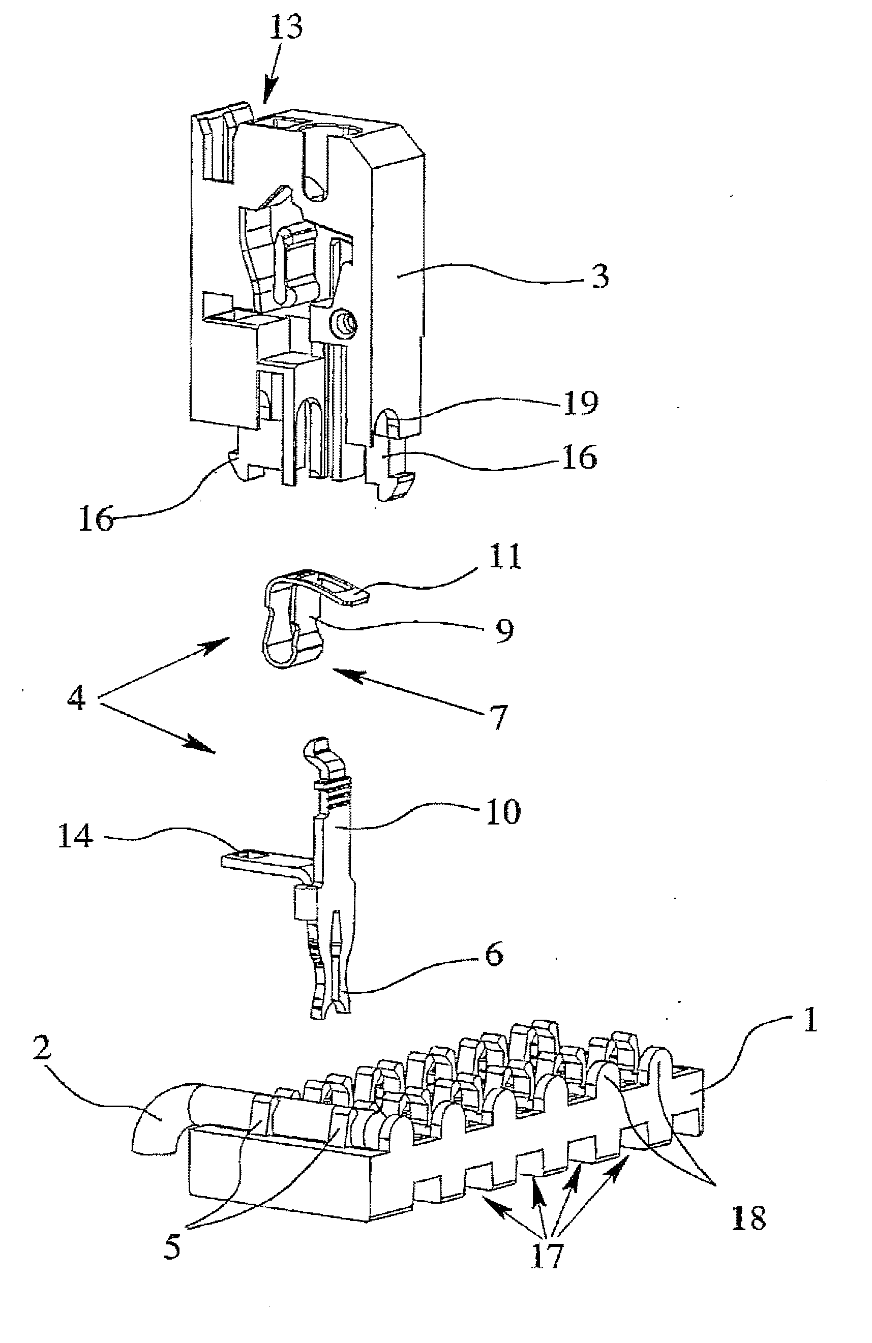
[0028] The electrical arrangement in accordance with the invention is described below for connection of an electric motor using several preferred embodiments. The invention could also be equally well described using other applications for connection of other electrical devices; the electrical connection arrangement in accordance with the invention is completely independent of the special application and function of the electrical device which is to make contact with the electrical connection arrangement.

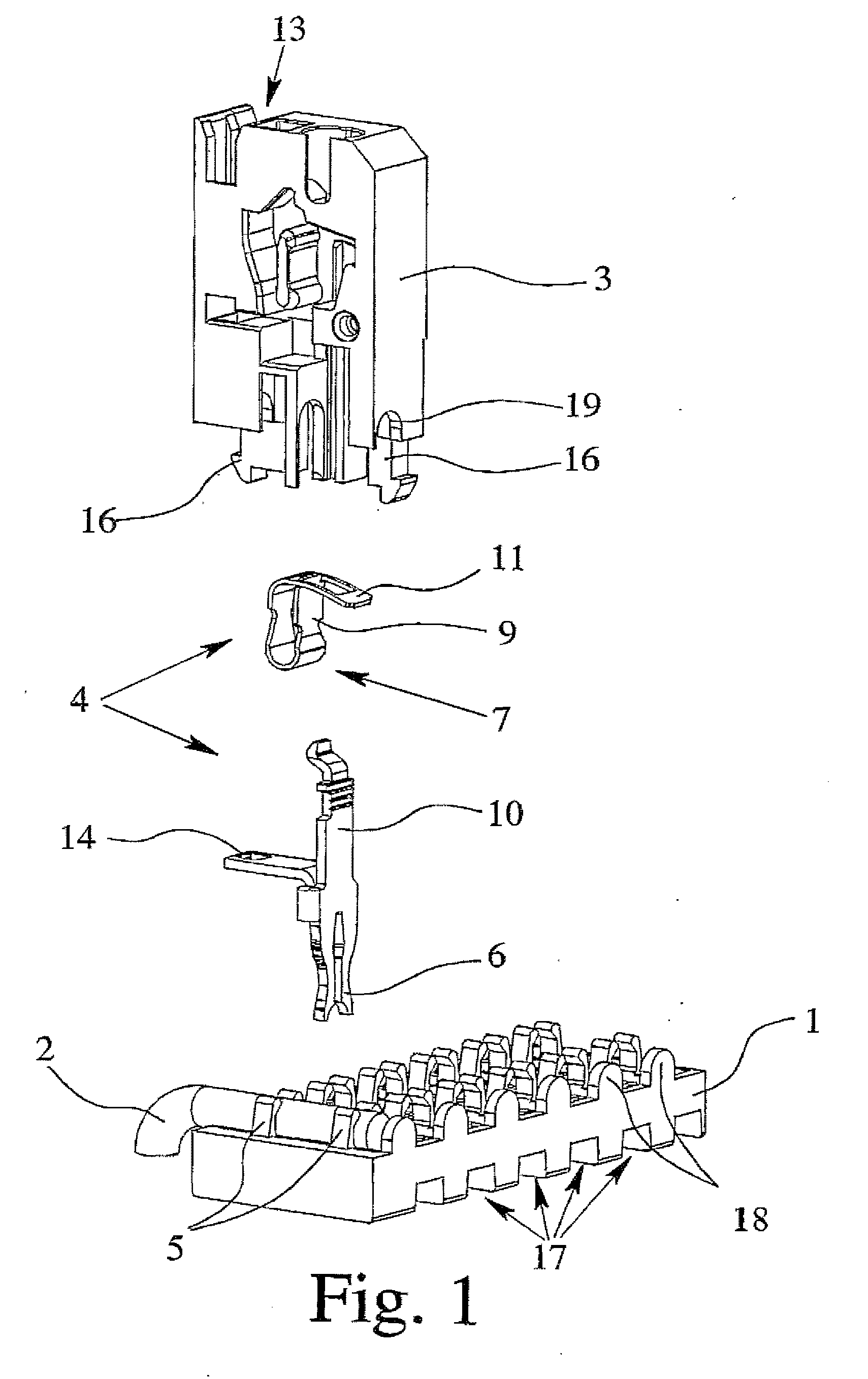
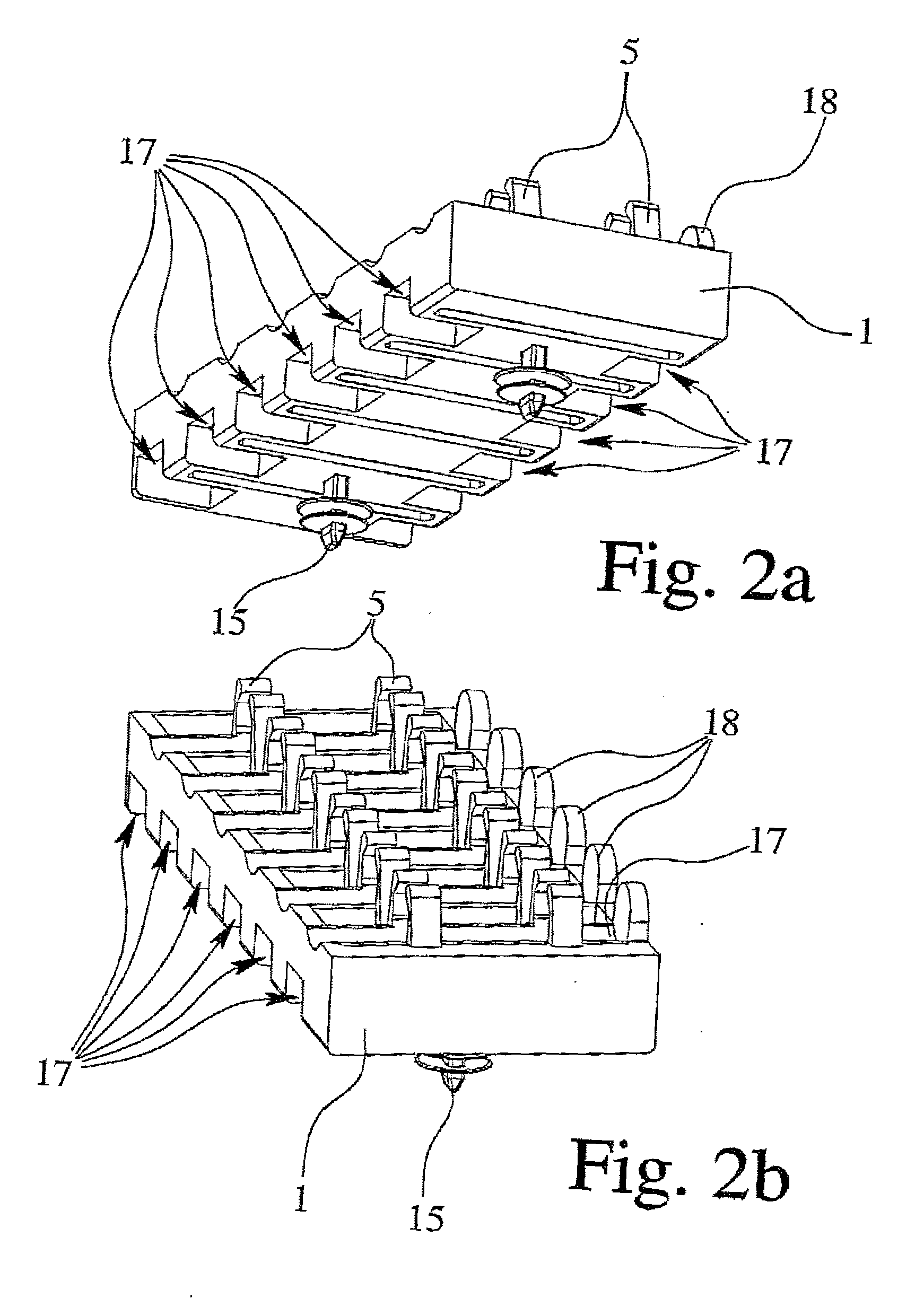
[0029]FIG. 1 shows, in an exploded view using one preferred embodiment, the important components of the connection arrangement in accordance with the invention, having a bottom part 1 which is used to hold the device-side cable 2, a top part 3 for holding a connection-side cable (not shown here) and a contact body 4 by which an electrical connection is established between the device-side cable 2 and the connection-side cable. Furthermore, the bottom part 1 is provided with fastening...


PUM


Abstract

An electrical connection arrangement for electrical connection of an electrical device with a bottom part for holding at least one device-side cable, with a top part for holding at least one connection-side cable and with a contact body for electrical connection of the device-side cable to the connection-side cable, the bottom part and the top part being formed essentially of an electrically insulating material. The connection is improved in that at least one fastening device for fastening at least one device-side cable is formed in the bottom part, that the contact body is located in the top part and has a first contact device and a second contact device, and that, in the joined position of the bottom part to the top part, the contact body makes contact with the device-side cable with the first contact device and makes contact with the connection-side cable with the second contact device.

Description

BACKGROUND OF THE INVENTION [0001] 1. Field of the Invention [0002] The invention relates to an electrical connection arrangement for electrical connection of an electrical device, especially an electric motor, with a bottom part for holding at least one device-side cable, with a top part for holding at least one connection-side cable and with a contact body for electrical connection of the device-side cable to the connection-side cable, the bottom part and the top part being formed essentially of an electrically insulating material. [0003] 2. Description of Related Art [0004] Electrical connection arrangements of the type under consideration are known and are used for quite different contact-making and connection purposes. From plant construction for example terminal blocks are known which are designed conventionally for top-hat rail installation in a switching cabinet and consist of a bottom part and a top part (Phoenix Contact product catalog, COMBICON® Circuit board connection, ...

Claims


Application Information

Patent Timeline
Patent Type & Authority Applications(United States)
IPC IPC(8): H01R4/24
CPCH01R4/2433H01R2201/22H01R4/4836H01R4/48365
Inventor REIBKE, HEINZ
Owner PHOENIX CONTACT GMBH & CO KG
Why Eureka
Try Eureka