Display apparatus, method, and program

a technology of display apparatus and display method, applied in the direction of user interface execution, television system, instruments, etc., can solve the problems of third window being hidden or hidden by a third window, content displayed by the rear window is hidden and unseen, and cannot be completely avoided

Inactive Publication Date: 2007-03-01
KK TOSHIBA
View PDF20 Cites 56 Cited by
  • Summary
  • Abstract
  • Description
  • Claims
  • Application Information

AI Technical Summary

Problems solved by technology

Although it is possible to effectively use the desktop area by utilizing window overlapping, the overlapping causes trouble that contents displayed by the rear window are hidden and unseen.
If the position of the rear window is moved, however, then there is a possibility that a problem that a third window is hidden or the rear window is hidden by a third window will occur.
Even if a contrivance such as downscaling of the window at the time of movement is conducted, this problem cannot be completely avoided.
However, hardness to see caused by the fact that overlapping contents of the two windows are displayed poses a problem.
On the other hand, even if a technique of moving the start position of data displayed in a ...

Method used


Image

  • Display apparatus, method, and program
  • Display apparatus, method, and program
  • Display apparatus, method, and program

Examples


first embodiment

[0055] Hereafter, a first embodiment of the present invention will be described with reference to FIGS. 1 to 21.

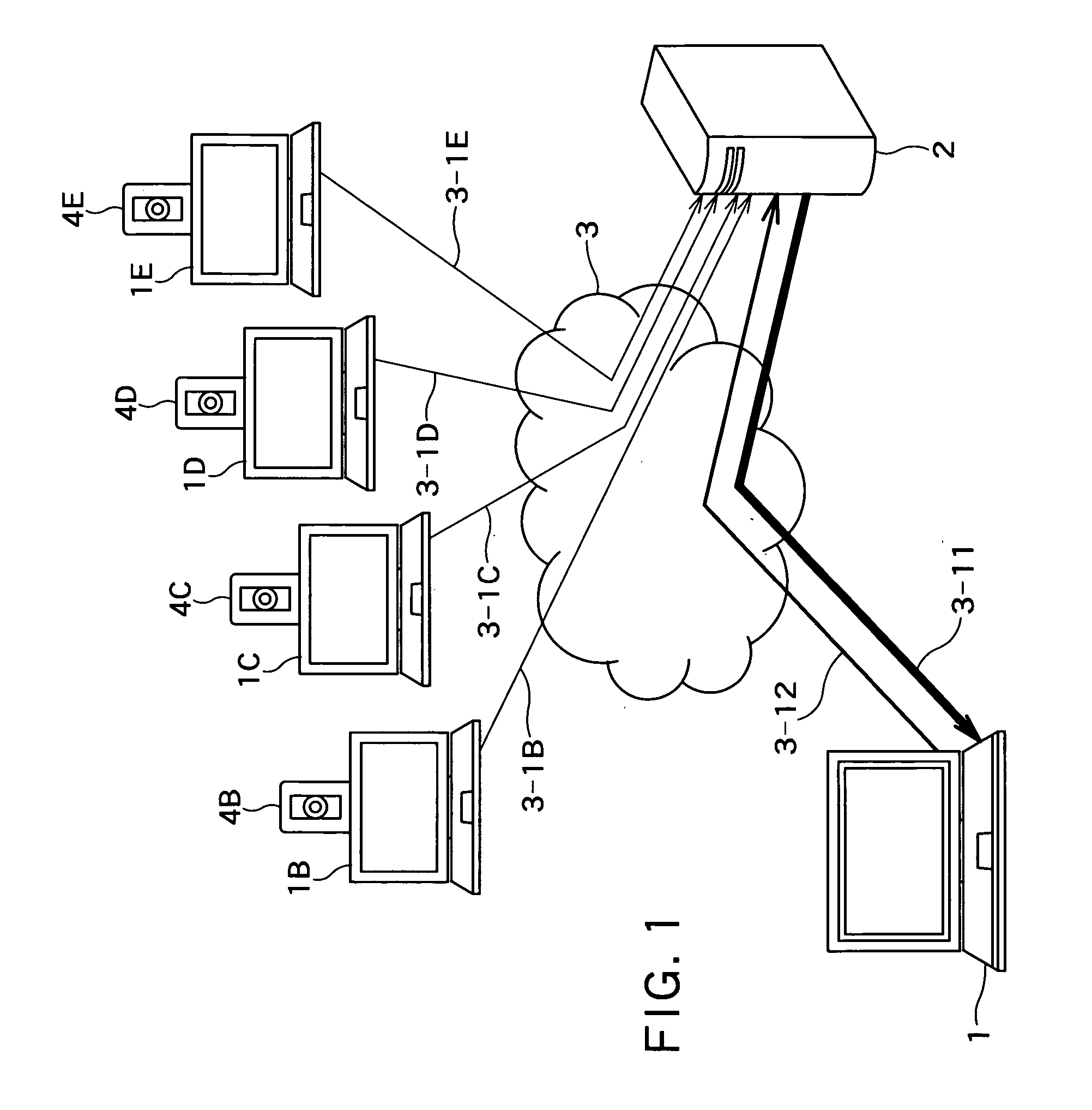
[0056]FIG. 1 shows a system configuration of a multipoint video conference system according to the present invention. FIG. 1 shows an example of the case where video conference is conducted at five points. The system shown in FIG. 1 includes conference terminals 1, 1B, 1C, 1D and 1E and a conference server 2. The conference terminals 1, 1B, 1C, 1D and 1E are connected to the conference server 2 via a network 3.

[0057] In the present embodiment, the conference terminals 1B, 1C, 1D and 1E have a function of transmitting video data to the conference server 2 by utilizing communication paths 3-1B, 3-1C, 3-1D and 3-1E, respectively. The conference server 2 has a function of composing video images received from the conference terminals 1B, 1C, 1D and 1E into one video image in a state in which the conference server 2 is connected simultaneously to the conference terminals 1, 1B...

second embodiment

[0085] Hereafter, a second embodiment of the present invention will be described with reference to FIGS. 22 to 24, FIG. 2, FIGS. 5 to 7, and FIGS. 17 to 19.

[0086]FIG. 22 shows an internal configuration of a display apparatus 4 according to the present embodiment. The display apparatus 4 is, for example, a personal computer (hereafter referred to as PC) or PDA (Personal Digital Assistant) having a function of conducting communication via a network. The present embodiment will now be described supposing that the display apparatus 4 is a PC of notebook type having the Windows OS of the Microsoft Corporation mounted thereon.

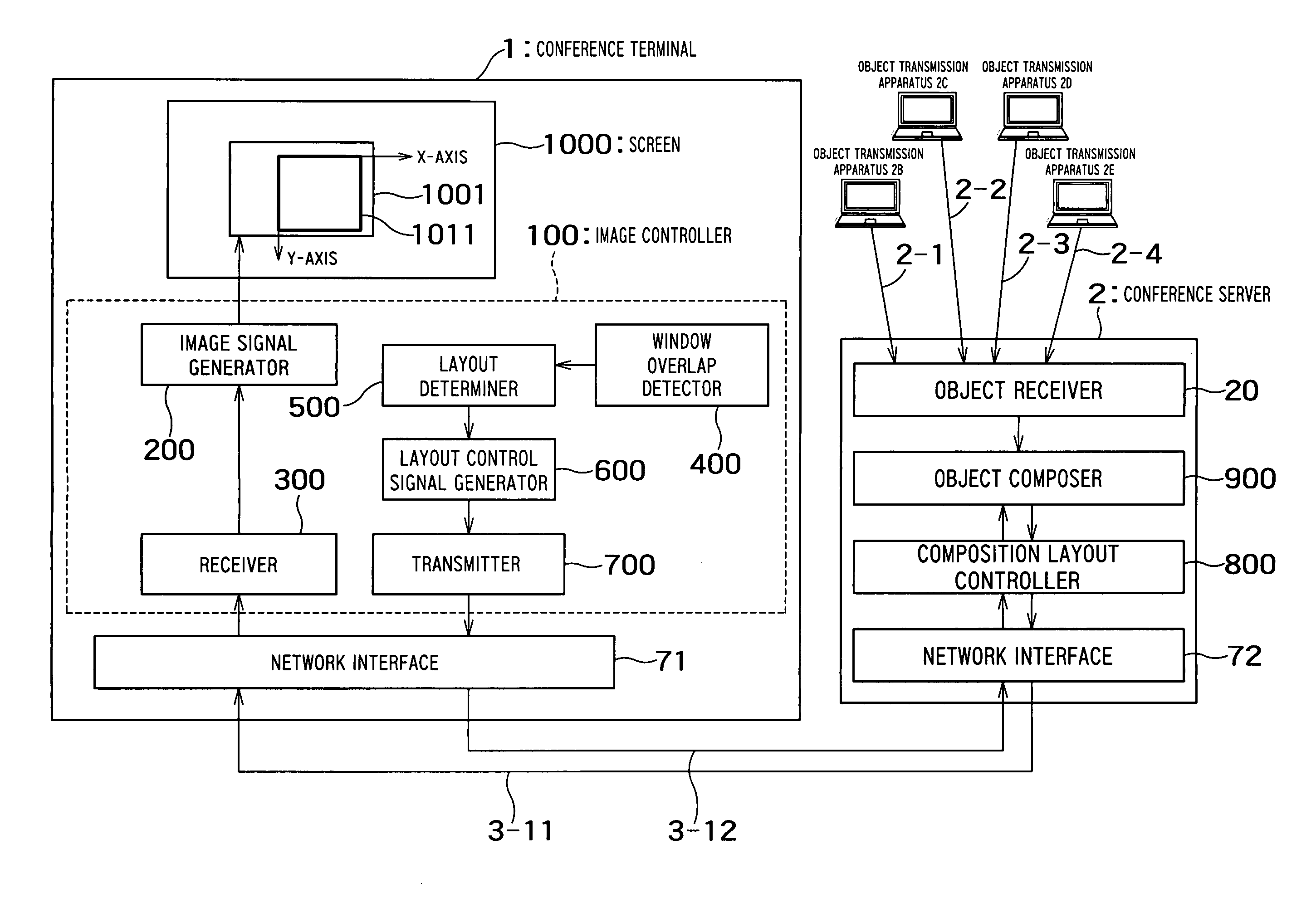
[0087] The display apparatus 4 includes an image controller 100 which is a feature of the present embodiment, as its component. The image controller 100 can cause a screen 1000 to display drawing data generated internally using a drawing function mounted on the PC. The image controller 100 can receive objects from object transmission apparatuses 2B, 2C, 2D and 2E b...

third embodiment

[0108] Hereafter, a third embodiment of the present invention will be described with reference to FIGS. 25A to 32B.

[0109] The present embodiment shows concrete examples of the method in which the window overlap detector 400 described in the first embodiment and the second embodiment detects overlapping of a different window, and the method in which the layout determiner 500 calculates and determines the layout information so as to avoid the overlapping area on the basis of the overlapping quantity.

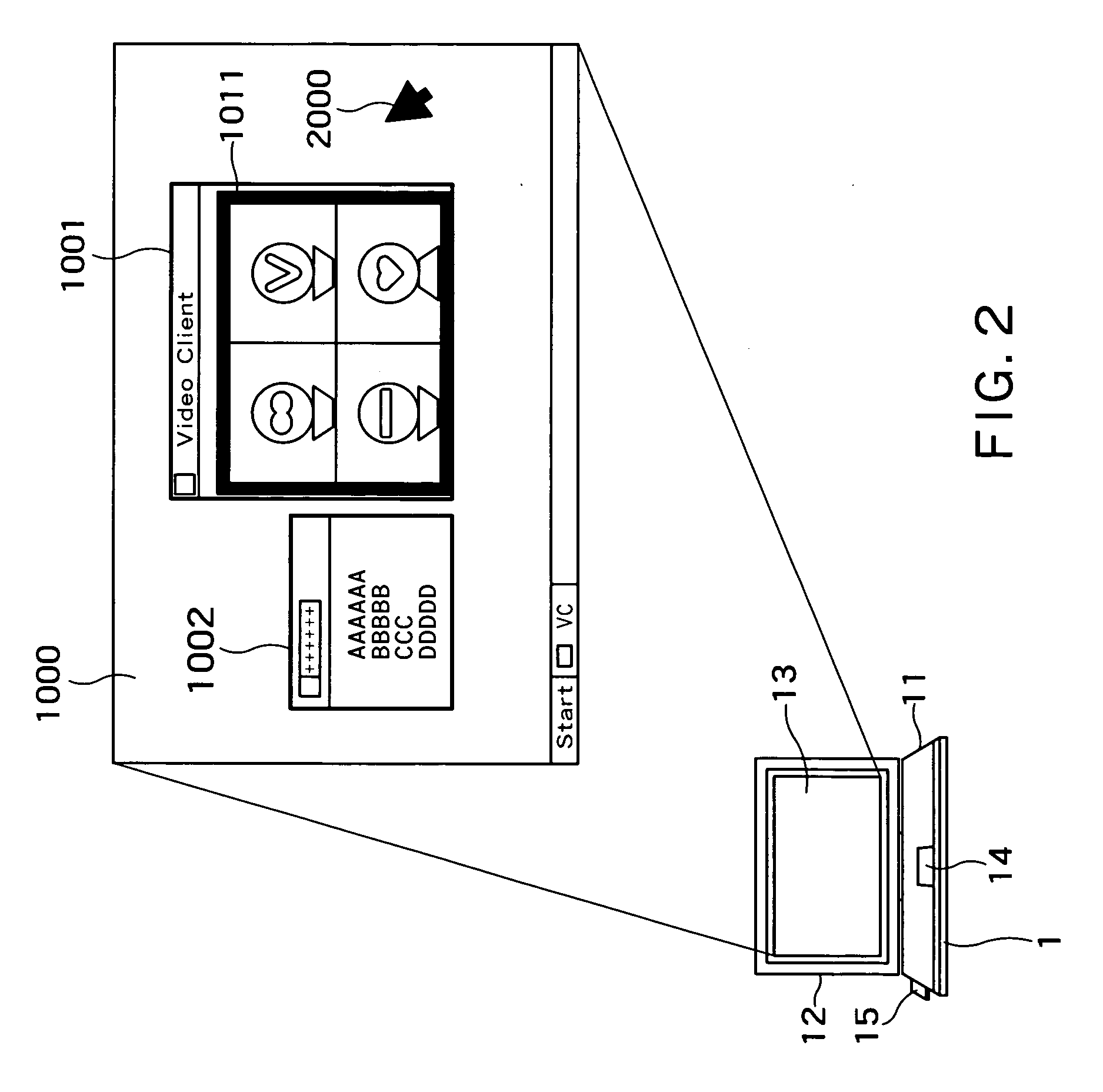
[0110] The window overlap detector 400 has a function of detecting that a different opaque window 1002 overlaps its own window 1001. For example, if the Windows OS of the Microsoft Corporation is mounted as the OS, a technique for detecting that a different front opaque window overlaps a certain window by utilizing the function of Win32 API provided by the system is self-evident. It becomes possible to recognize the position and size of the different window 1002 by, for example, acquirin...


PUM


Abstract

There is provided with a display apparatus including: a display apparatus which displays a first window and a second window, comprising: a receiver configured to receive a composite object obtained by composing a first object and a second object, from a server; a display unit configured to display the composite object in the first window; a window overlap detector configured to detect an overlap between the second window and the composite object in the first window, and to obtain a position of the overlap in the first window; a layout determiner configured to determine layouts of the objects in the composite object according to the position of the overlap so as not to place the first object and the second object on the position of the overlap; and a transmitter configured to transmit information of the layouts of the objects determined by the layout determiner, to the server.

Description

CROSS-REFERENCE TO RELATED APPLICATIONS [0001] This application is based upon and claims the benefit of priority from the prior Japanese Patent Applications No. 2005-252042 filed on Aug. 31, 2005, the entire contents of which are incorporated herein by reference. BACKGROUND OF THE INVENTION [0002] 1. Field of the Invention [0003] The present invention relates to a display apparatus, a display method, and a program, which display, for example, a composite video image in a multipoint video conference system utilizing an image composition server. [0004] 2. Related Art [0005] As the graphical user interface develops, it is possible in personal computers (PCs) of today to display a plurality of windows on a display (called desktop as well). The display windows are managed by a window display system. The user conducts work while freely operating the windows on the desktop. Among a plurality of display windows, a window which accepts user's operation is called active window. Furthermore, t...

Claims


Application Information

Patent Timeline
IPC IPC(8): G06F17/00G06F3/00G06F3/048G06F3/0484
CPCH04N7/147G06F9/4445G06F9/4443H04N7/152G06F9/452G06F9/451
Inventor KAWAMURA, TAKUYAKAWAZOE, HIROSHI
Owner KK TOSHIBA
Why Eureka
Try Eureka