
Optical disc drive

a technology of optical disc drives and optical discs, applied in the field of optical disc drives, can solve the problems of increasing friction between components, increasing problems, and generating noise due to gaps, so as to prevent a large load from being applied, prevent shaking of the tray, and minimize vibration and noise.

Inactive Publication Date: 2007-03-01
SAMSUNG ELECTRONICS CO LTD
View PDF5 Cites 1 Cited by
  • Summary
  • Abstract
  • Description
  • Claims
  • Application Information

AI Technical Summary

Benefits of technology

[0013] Therefore, it is an aspect of the invention to provide an optical disc drive that is capable of restricting the lateral and vertical movement of a tray when a loading operation of the tray is completed to minimize vibration and noise generated when the disc is recorded / reproduced. It is another aspect of the invention to provide an optical disc drive that is capable of preventing a large load from being applied to a loading motor. It is yet another aspect of the invention to provide an optical disc drive that is capable of preventing shaking of the tray when an unloading operation of the tray is completed.

Problems solved by technology

When the disc is recorded / reproduced, however, noise is generated due to the gaps.
This problem is increased as high-speed recording / reproducing technology is advanced (for example, 52-X for CDs and 16-X for DVDs).
As a result, friction between the components is increased when the tray 2 is slid, and therefore, a large load is applied to the loading motor.

Method used


Image

  • Optical disc drive
  • Optical disc drive
  • Optical disc drive

Examples


Embodiment Construction

[0024] Reference will now be made in detail to the embodiment of the present invention, examples of which are illustrated in the accompanying drawings, wherein like reference numerals refer to like elements throughout. The embodiments are described below to explain the present invention by referring to the figures.

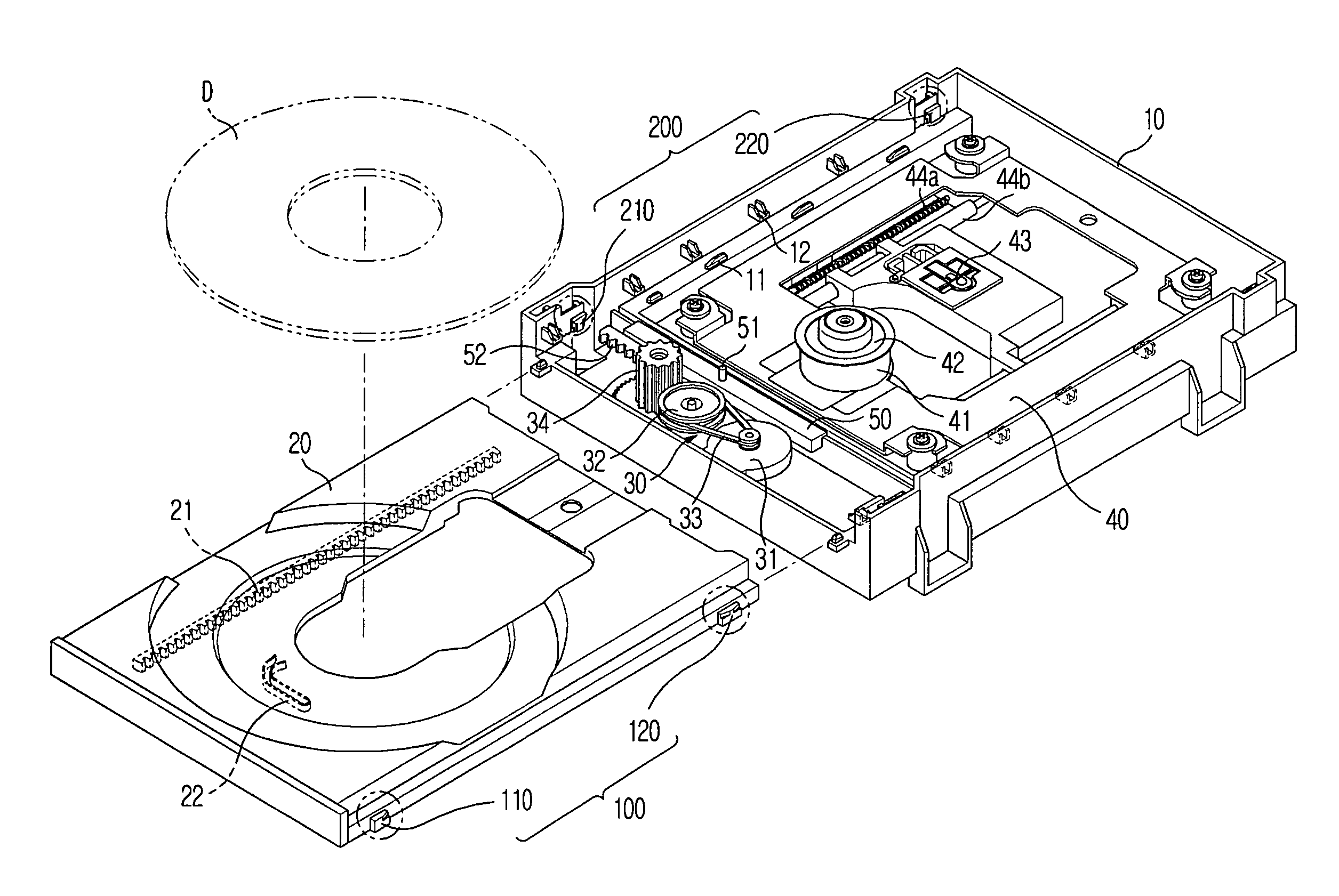
[0025]FIG. 4 is a perspective view illustrating the structure of an optical disc drive according to the present invention. As shown in FIG. 4, the optical disc drive includes a main frame 10 and a tray 20, which is disposed such that the tray 20 is inserted into or ejected from the main frame 10 to load or unload a disc D. The tray 20 is slid through the front part, which is open, of the main frame 10 to perform a loading / unloading operation.

[0026] A loading unit 30 to provide power necessary to slide the tray 20 is mounted at a bottom surface of the front part of the main frame 10. The loading unit 30 includes a loading motor 31, and a pulley 32, a belt 33, and a pinion...


PUM


Abstract

An optical disc drive, including a main frame a tray disposed such that the tray is to be inserted into or ejected from the main frame to load or unload a disc and a tray holding unit to press bias the tray, when the loading / unloading of the tray is completed, so as to restrict the vertical and lateral movement of the tray when the loading / unloading of the tray is completed.

Description

CROSS-REFERENCE TO RELATED APPLICATIONS [0001] This application claims the benefit of Korean Patent Application No. 2005-79906, filed Aug. 30, 2005 in the Korean Intellectual Property Office, the disclosure of which is incorporated herein by reference. BACKGROUND OF THE INVENTION [0002] 1. Field of the Invention [0003] Aspects of the present invention relate to an optical disc drive, and, more particularly, to an optical disc drive that is capable of preventing shaking of a tray, thereby minimizing vibration and noise generated from the tray. [0004] 2. Description of the Related Art [0005] Generally, an optical disc drive is an apparatus that irradiates light to a disc-shaped optical medium (hereinafter, referred to as a “disc”), such as a compact disc (CD), a digital versatile disc (DVD), or a blu-ray disc (BD), to record data to the disc or reproduce data from the disc. [0006]FIG. 1 is a perspective view schematically illustrating a conventional optical disc drive, and FIG. 2 is a...

Claims


Application Information

Patent Timeline
IPC IPC(8): G11B17/04
CPCG11B17/05G11B17/03G11B17/04
Inventor YIM, HONG KYUNLEE, YONG HOONEUM, JAE-YONGLEE, JEUNG RAK
Owner SAMSUNG ELECTRONICS CO LTD
Features
  • Generate Ideas
  • Intellectual Property
  • Life Sciences
  • Materials
  • Tech Scout
  • Unparalleled Data Quality
  • Higher Quality Content
  • 60% Fewer Hallucinations
Learn More