Archery bowstring peep sight useful in low light conditions

Inactive Publication Date: 2007-03-08
MYERS RONALD C
View PDF17 Cites 11 Cited by
  • Summary
  • Abstract
  • Description
  • Claims
  • Application Information

AI Technical Summary

Benefits of technology

[0008] It has been found that when used in low ambient light conditions, the drawback to conventional peep sights is that when an archer draws on a target, the archer is at best able to view a limited portion of the target, for example, only the body of the intended target. In accordance with the present invention, this drawback is overcome by enabling the archer to also see above and below the intended target. This not only provides a full view of the target, but also enhances depth perception.
[0009] This is accomplished by providing a peep sight which is generally comprised of a body which develops a frame for defining a shaped aperture and which includes a peripheral groove for receiving a bowstring, for mounting the peep sight to the bowstring. The shaped aperture which is developed by the frame forms a single, vertically elongated sight window. The elongated shape of the frame also facilitates mounting of the peep sight to a conventional, multi-stranded bowstring.
[0010] It has surprisingly been found that, contrary to the general belief that a peep sight which provides a larger sight picture, although easier to sight through, would lack precision, the relatively large, elongated shape of the peep sight of the present invention makes the viewing of a target much easier, especially in low light situations. Moreover, the thin frame and the large viewing area of the peep sight of the present invention allows the eye of the archer to gather more light, yielding a better view of the intended target, particularly in low light conditions.
[0011] In use, the peep sight of the present invention allows an archer to immediately focus on the sighting pins of the bow, and then on the target, without any obstruction. The shape of the peep sight of the present invention allows the archer to more easily center the sighting pins, by moving to the left or to the right, while the selected anchoring point controls elevation. As a result, and contrary to expectations, the relatively large peep sight of the present invention has been found to be more accurate in use.

Problems solved by technology

It has been found that when used in low ambient light conditions, the drawback to conventional peep sights is that when an archer draws on a target, the archer is at best able to view a limited portion of the target, for example, only the body of the intended target.

Method used


Image

  • Archery bowstring peep sight useful in low light conditions
  • Archery bowstring peep sight useful in low light conditions
  • Archery bowstring peep sight useful in low light conditions

Examples


Embodiment Construction

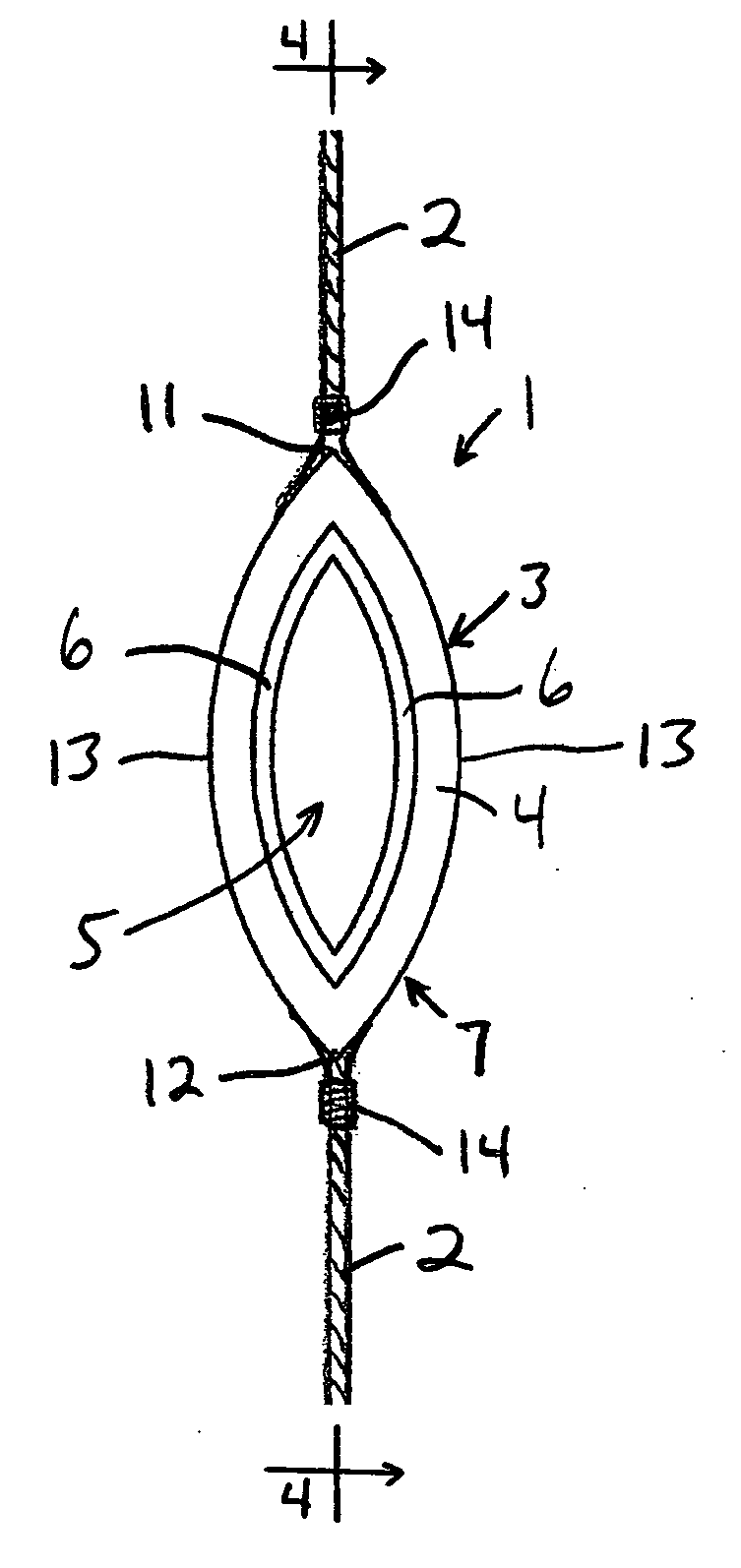
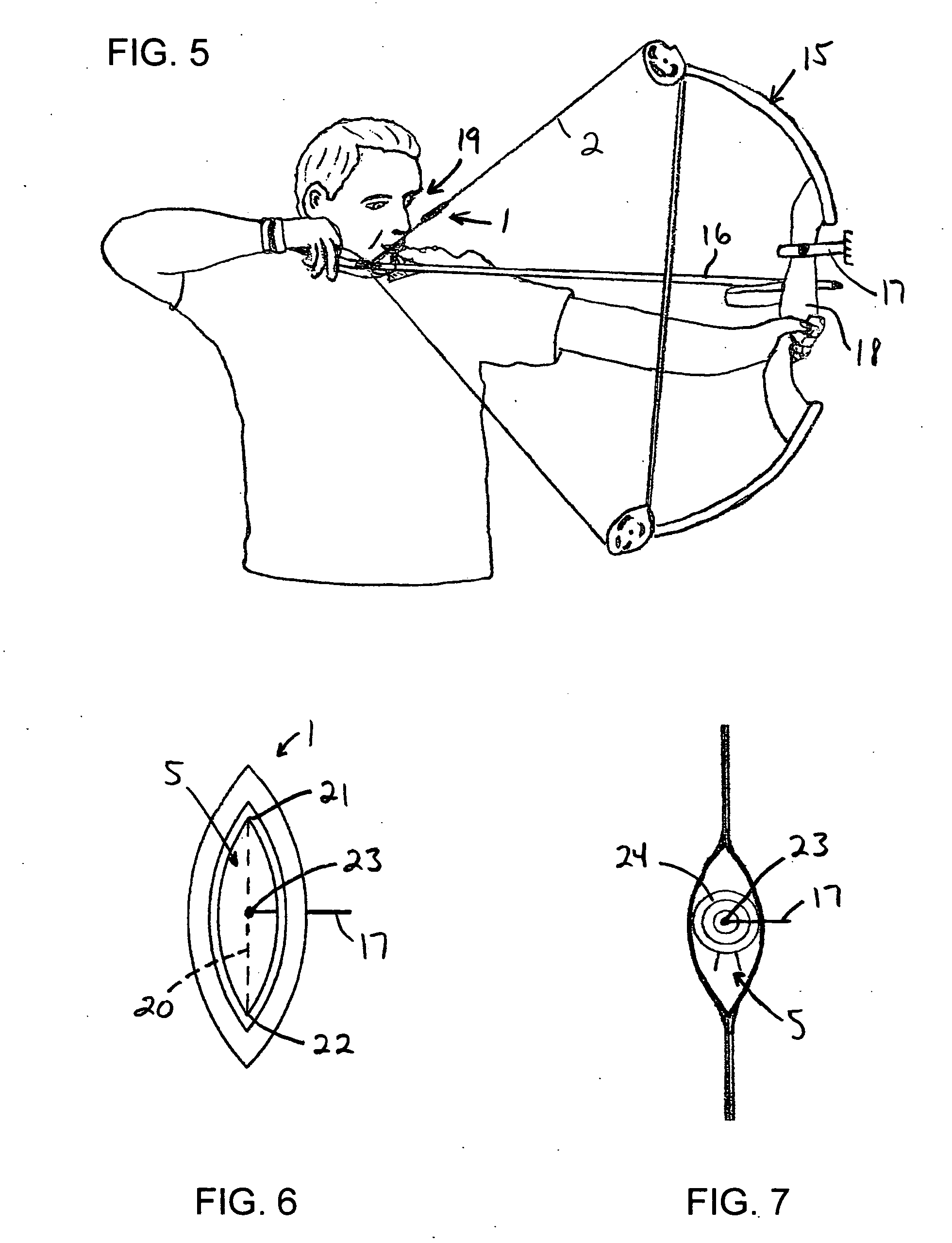
[0020]FIG. 1 shows a peep sight 1 which is produced in accordance with the present invention, mounted to a bowstring 2 associated with desired archery equipment. The bowstring 2 is, itself, entirely conventional in configuration, and is provided only for purposes of illustration. The bowstring 2 can be mated with any of a variety of different types of archery equipment, as will be discussed more fully below.

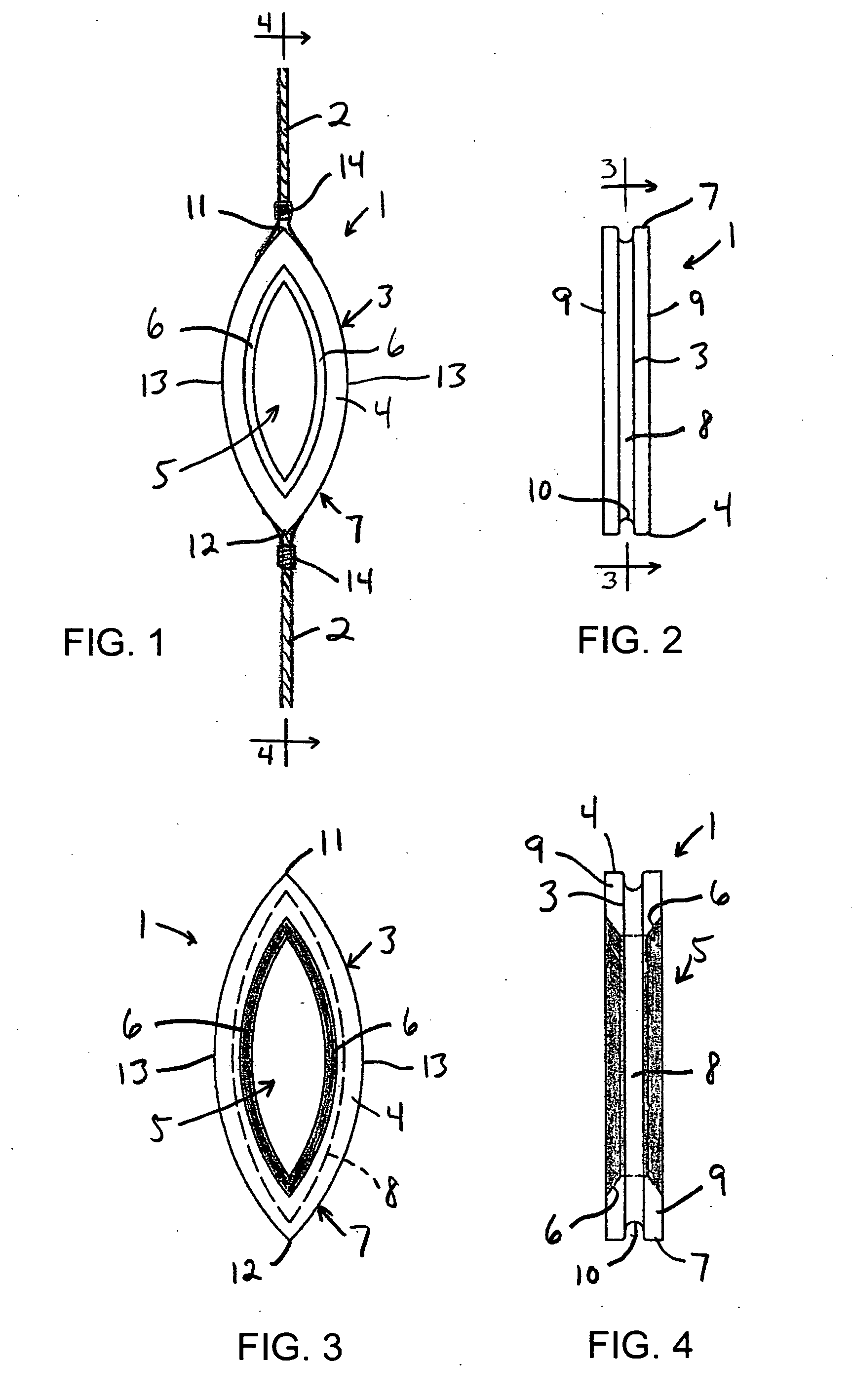
[0021] The peep sight 1 shown in FIG. 1 generally takes the form of a solid body 3 which develops a frame 4 for defining an aperture 5 which extends through the body 3. The aperture 5 is elongated in height, relative to the width of the aperture 5, and is preferably elliptical in shape, as illustrated. Edges 6 of the frame 4 adjacent to the aperture 5 are preferably beveled, as shown, to help gather light and to allow more light to enter the aperture 5, facilitating use of the peep sight 1 during low light conditions.

[0022] Referring to FIG. 2, the periphery 7 of the body 3 inc...


PUM


Abstract

A peep sight which enables viewing above and below an intended target includes a body which develops a frame for defining a shaped aperture and a peripheral groove for receiving a bowstring, for mounting the peep sight to the bowstring. The shaped aperture forms a single, vertically elongated sight window which provides a large sight picture to facilitate viewing of the target, especially in low light situations, and which is free of internal structures. In use, the peep sight allows an archer to immediately focus on the sighting pins of the bow, and then on the target, without obstruction.

Description

BACKGROUND OF THE INVENTION [0001] The present invention generally relates to a device useful for aligning archery equipment with desired targets, and more particularly, to an alignment device of the type generally referred to as a “peep sight”. [0002] A great number of devices have been developed for use with various different types of archery equipment in an effort to improve the accuracy of the process for aligning the arrow which is to be released from the bow with an intended target, i.e., aiming of the archery equipment. The subject matter of the present invention is primarily directed to one such type of aiming device, which is commonly referred to as a “peep sight”, which have long been used with many types of weapons that require alignment with an object or a target. [0003] For use in archery, peep sights are conventionally associated with the bowstring of the archery equipment, and are used to establish an orientation for the bow relative to the intended target. Orientatio...

Claims


Application Information

Patent Timeline
IPC IPC(8): F41G1/467
CPCF41G1/467F41B5/14F41B5/1419F41G1/01
Inventor MYERS, RONALD C.
Owner MYERS RONALD C
Why Eureka
Try Eureka