Packaging for surgical blade tips

Active Publication Date: 2010-10-07
BEAVER VISITEC INT US
View PDF14 Cites 5 Cited by
  • Summary
  • Abstract
  • Description
  • Claims
  • Application Information

AI Technical Summary

Benefits of technology

[0003]A package for a surgical blade tip is provided herein. The package cooperates with the surgical blade tip to properly retain it and facilitate mounting onto a surgical blade handle. In one aspect, the invention includes a package having a body with a side wall and at least two detents extending inwardly from the side wall. In addition, a surgical blade tip is provided having an adaptor with a blade extending therefrom. The adaptor includes at least two recesses formed therein. The surgical blade tip is disposed in the package with the detents being at least partially inserted into the recesses. Also, the detents are configured to apply a retentive force to the adaptor to retain the adaptor in a first position and configured to deflect with a predetermined amount of torque being applied to the surgical blade tip so as to permit the adaptor to rotate relative to the body from the first position to a second position where the detents are not inserted into the recesses. Advantageously, with the subject invention, a package may be provided which maintains a blade of a surgical blade tip in spaced relationship so as to minimize contamination thereof. In addition, the interengagement of the detents and the recesses allows for proper retention of the surgical blade tip during mounting onto a surgical blade handle.

Problems solved by technology

This is a typically unsafe operation due to an exposed point or cutting edge.
Due to the structure of the collet, sterilization may be difficult.
In addition, the collet is often misplaced or lost and must be replaced for use.

Method used


Image

  • Packaging for surgical blade tips
  • Packaging for surgical blade tips
  • Packaging for surgical blade tips

Examples


Embodiment Construction

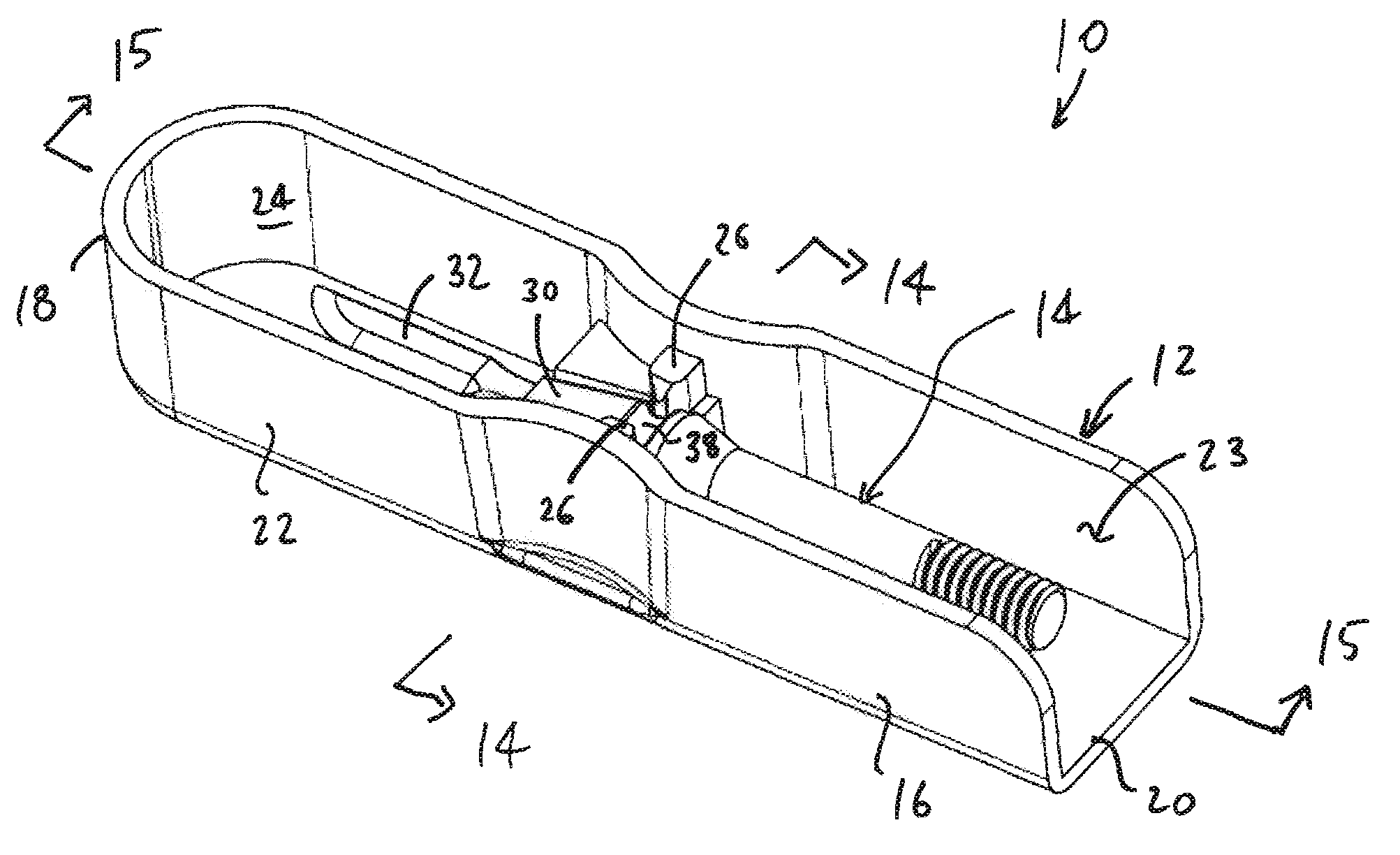
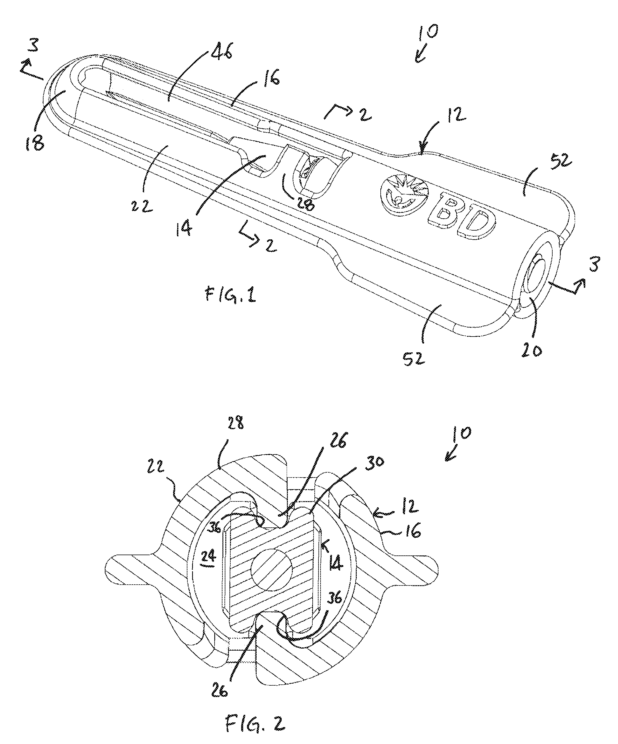
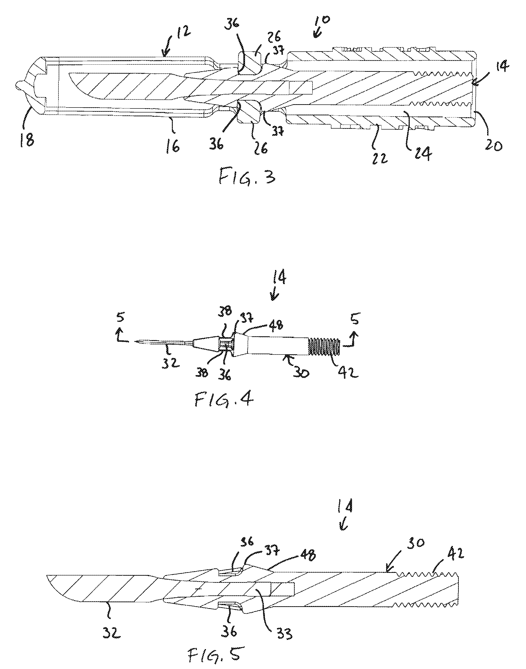
[0020]With reference to the Figures, a combination 10 is shown of a package 12 with a surgical blade tip 14 being disposed therein. The combination 10 is sterilizable for operating room use and an outer pouch may be provided in which the combination 10 is packaged to maintain sterility thereof.

[0021]The package 12 includes a body 16 with a closed end 18, an open end 20 and a side wall 22 extending therebetween. The body 16 defines an interior 24 formed to accommodate the surgical blade tip 14, preferably, with no portion of the surgical blade tip 14 extending therefrom. At least two detents 26 extend inwardly from the side wall 22 into the interior 24, with, preferably, two of the detents 26 being provided which are disposed at diametrically opposite locations on the body 16. The detents 26 are formed to be deflectable. With reference to FIG. 1, the detents 26 may be formed on cantilevered arms 28 formed in the side wall 22. Outward deflection of the detents 26 may be obtained by ca...


PUM

PropertyMeasurementUnit
Angleaaaaaaaaaa
Forceaaaaaaaaaa

Abstract

A package for a surgical blade tip is provided herein. The package cooperates with the surgical blade tip to properly retain it and facilitate mounting onto a surgical blade handle. In one aspect, the invention includes a package having a body with a side wall and at least two detents extending inwardly from the side wall. In addition, a surgical blade tip is provided having an adaptor with a blade extending therefrom. The adaptor includes at least two recesses formed therein. The surgical blade tip is disposed in the package with the detents being at least partially inserted into the recesses. Also, the detents are configured to apply a retentive force to the adaptor to retain the adaptor in a first position and configured to deflect with a predetermined amount of torque being applied to the surgical blade tip so as to permit the adaptor to rotate from the first position to a second position where the detents are not inserted into the recesses. Advantageously, with the subject invention, a package may be provided which maintains a blade of a surgical blade tip in spaced relationship so as to minimize contamination thereof. In addition, the interengagement of the detents and the recesses allows for proper retention of the surgical blade tip during mounting onto a surgical blade handle.

Description

FIELD OF THE INVENTION[0001]This invention relates to packaging for surgical blade tips.DESCRIPTION OF THE PRIOR ART[0002]Packaging for surgical blade tips is known in the prior art. In the prior art, surgical blade tips are typically offered in two forms, those that require collets for assembly to surgical blade handles and those that are in plastic tips that do not require collets for assembly to the surgical blade handles. Both forms of blade tips are assembled by hand or the use of a mechanical device such as a hemostat. This is a typically unsafe operation due to an exposed point or cutting edge. Surgical blade handles are typically provided with a collet which is used re-usably with single-use packaged surgical blade tips. The blade handle is sterilized between uses, including the collet. Due to the structure of the collet, sterilization may be difficult. In addition, the collet is often misplaced or lost and must be replaced for use. In the prior art, surgical blades with pla...

Claims


Application Information

Patent Timeline
IPC IPC(8): A61B19/02B23P11/00
CPCY10T29/49826A61B2019/4805A61B2017/0046A61B17/3215A61B19/0262A61B50/3001A61B2090/0801
Inventor COTE, DANADEMARINIS, ROBERTHALLORAN, GREGORY P.WALSH, THOMAS F.CHIAPPONE, JESSICA
Owner BEAVER VISITEC INT US
Why Eureka
Try Eureka