Electrical switch

Inactive Publication Date: 2007-03-08
LEAR CORP
View PDF12 Cites 6 Cited by
  • Summary
  • Abstract
  • Description
  • Claims
  • Application Information

AI Technical Summary

Benefits of technology

[0009] The invention further provides a rotary electrical switch having a plurality of switch positions. The switch includes a rotatable knob for selecting the switch positions. A cavity having an open end and a closed end is disposed within the knob. The rotary electrical switch also includes a circuit board and a plurality of stationary first contacts disposed in the circuit board. A second contact includes a plurality of contact arms configured to move relative to the first contacts when the knob is rotated, and to electrically connect at least two of the first contacts when the knob is rotated to a predetermined position. An electrically insulating carrier member includes an elongate portion at least partially disposed and linearly movable within the knob cavity. The carrier member cooperates with the second contact and the knob such that rotation of the knob to select the switch positions effects an associated rotation of the second contact arms. A biasing member is disposed in the knob cavity between the closed end of the cavity and the elongate portion of the carrier member for imparting a contact force to the second contact through the carrier member. This facilitates electrical contact between the second contact arms and the first contacts.

Problems solved by technology

One of the issues faced by any designer is the problem of determining tolerances for mating parts.
Moreover, the greater the number of parts, the greater the potential for tolerance stack-up problems.
One limitation of the switch described in Hollenbeck Jr. is that the spring is in direct contact with the electrical contact itself.
Another limitation is that the knob is attached to the switch via a threaded fastener and washer, which requires a cumbersome and time-consuming assembly process.
In addition, the rotary contact slides over a portion of the knob, such that even if the coil spring were isolated from the contacts, the knob would still be subject to whatever current flowed through the contacts.

Method used


Image

  • Electrical switch
  • Electrical switch
  • Electrical switch

Examples


Embodiment Construction

)

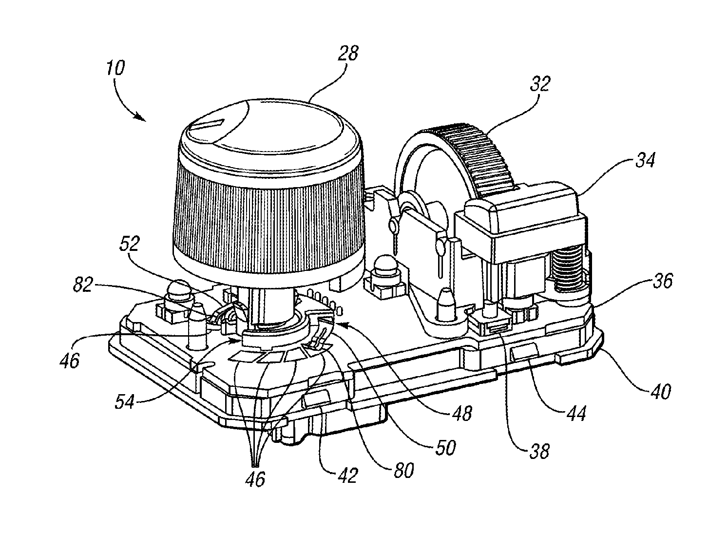
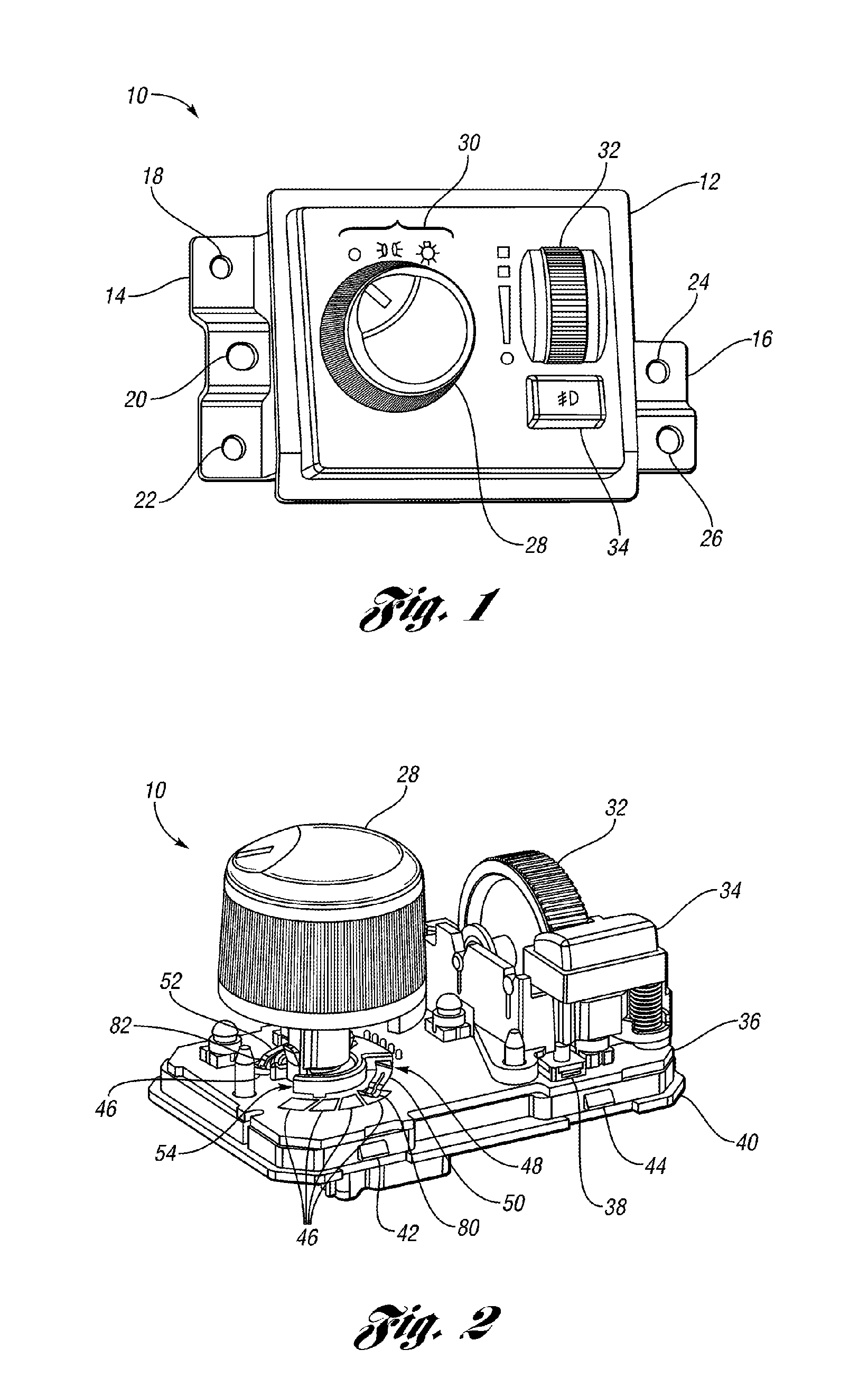
[0014] FIGS. 1 shows an electrical switch 10 in accordance with one embodiment of the present invention. The switch 10 is a compact device contained within a housing 12 having a pair of flanges 14, 16, for mounting the switch 10 to a support structure. Each of the flanges 14, 16 includes a number of apertures 18, 20, 22, 24, 26 disposed therethrough to receive a fastening element. The switch 10 is a type which may be conveniently used in a vehicle, for example, as a headlamp switch. The switch 10 includes a rotatable knob 28 which can be rotated to select a variety of switch positions, indicated by the icons 30 on the housing 12. The housing 12 may be conveniently made by an injection molding process, and it may be particularly convenient to use a polycarbonate (PC) material that is translucent, so that the icons 30 can be backlit for easy viewing by the vehicle operator during times of limited ambient light.

[0015] To further facilitate use of the space and components of the switc...


PUM


Abstract

An electrical switch having a plurality of switch positions includes a plurality of first electrical contacts, and a second electrical contact configured to electrically connect at least two of the first contacts. A carrier member is configured to carry the second contact, and a knob is used to facilitate selection of the switch positions. The knob is configured to cooperate with the carrier member so that moving the knob from one switch position to another results in a related movement of the carrier member and the second contact. A first biasing member, which is electrically isolated from all of the electrical contacts, is configured to bias at least a portion of the second contact toward the first contacts to facilitate an electrical connection therebetween.

Description

BACKGROUND OF THE INVENTION [0001] 1. Field of the Invention [0002] The present invention relates to an electrical switch. [0003] 2. Background Art [0004] Electrical switches are used in many different types of electrical and mechanical-electrical devices, including devices and systems within vehicles. With an ever increasing need to keep the cost of materials and production down, even relatively inexpensive items, such as electrical switches, are being targeted for cost savings. For example, reducing the total number of pieces in a switch, or making it easier to assemble, are two ways in which the overall cost of the switch may be reduced. One of the issues faced by any designer is the problem of determining tolerances for mating parts. Tolerances must be tight enough such that mating parts function properly together, while at the same time, not so tight that manufacturing costs are prohibitive. Moreover, the greater the number of parts, the greater the potential for tolerance stac...

Claims


Application Information

Patent Timeline
IPC IPC(8): H01H19/14
CPCH01H19/585H01H19/60H01H19/635
Inventor SALLAM, FAISAL K.FELDMAN, MARK G.MASTERS, BRIAN R.PIERIK, BRUCE
Owner LEAR CORP
Why Eureka
Try Eureka