Connection element

Active Publication Date: 2020-07-30
BJB GMBH & CO KG
View PDF6 Cites 0 Cited by
  • Summary
  • Abstract
  • Description
  • Claims
  • Application Information

AI Technical Summary

Benefits of technology

This patent describes a cover element that can be opened and closed to easily insert and remove a circuit board without tools. The cover element is secured in the closed position to ensure electrical contact with the circuit board and to prevent vibration. A contact pressure spring is used to preload the circuit board against the receiving element and compensate for fabrication tolerances. The cover element can be fixed in the open position to secure the connection element ready for mounting. The technical effect of this invention is to simplify the installation process and facilitate replacement of the circuit board without tools.

Problems solved by technology

Initial mounting and replacement, however, are comparatively uncomfortable.
The prior art lamps also have the disadvantage that they are not integratable into a lamp housing without great complexity.

Method used


Image

  • Connection element
  • Connection element
  • Connection element

Examples


Embodiment Construction

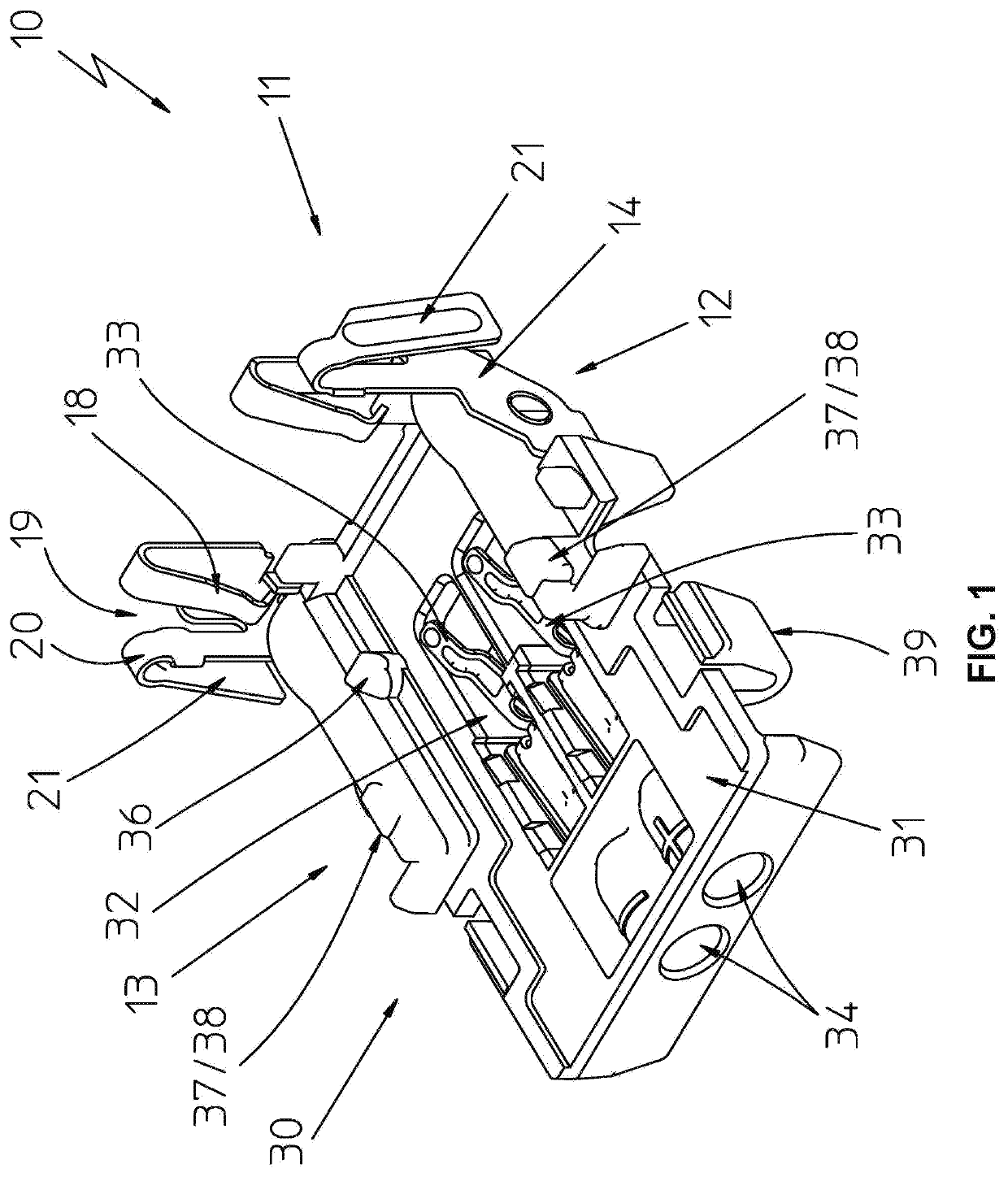
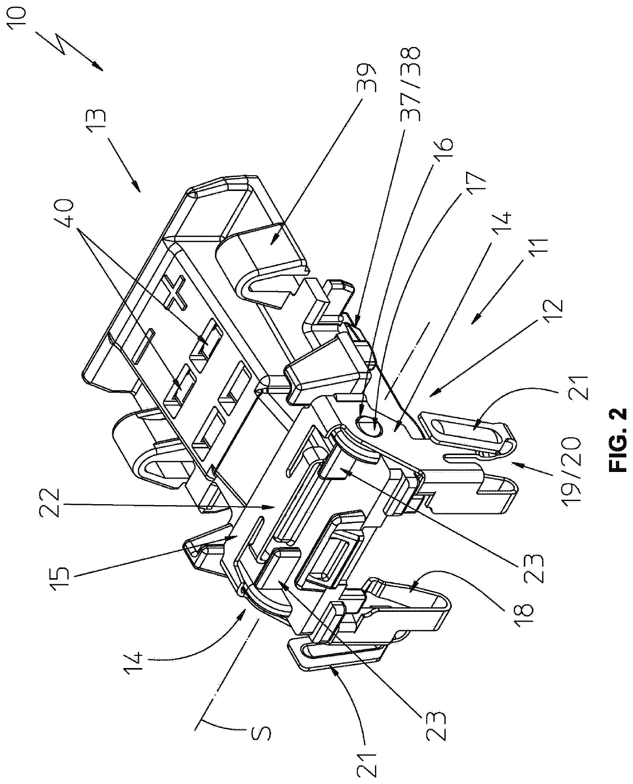
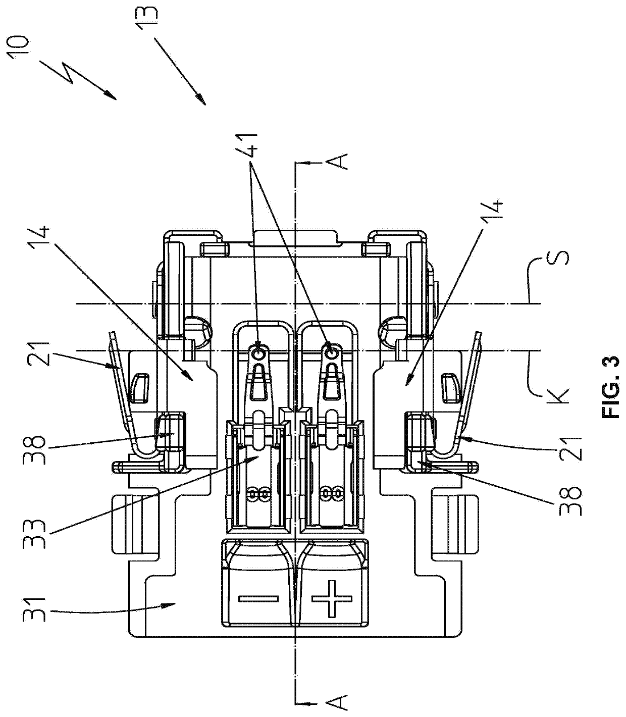
[0041]In the drawing figures the connection element according to the invention is designated overall with the reference numeral 10.

[0042]The connection element 10 is now described with reference to its structure based on FIGS. 1 and 2. The connection element includes a cover element 11 configured as a pivotable approximately a U-shaped bar 12 that is arranged at a receiving element 13 and pivotable about a geometric axis S and configured to receive the circuit board.

[0043]The U-shaped bar 12 includes two arms 14 that are oriented orthogonal to the pivot axis S wherein the ends of the arms that are oriented proximal to the pivot axis are connected with each other by a bridge 15 that is oriented parallel to the pivot axis. The arms 14 are furthermore provided with shaft openings 16 that are configured to receive stub shafts 17 that are formed by the receiving element 13. The stub shafts 17 form the physical pivot axis of the connection element 10.

[0044]The free ends of the arms 14 are...


PUM


Abstract

A connection element for a circuit board that includes electronic components or LED illuminants on a top side and that includes contact fields on a bottom side which are used at least for supplying electrical voltage to the electronic components that are arranged on the circuit board, the connection element including a receiving element that includes a contact surface for the circuit board and pressure contacts configured to contact the contact fields of the circuit board and connection contacts configured to connect connection conductors that provide electrical voltage; and a cover element that supports the circuit board on the receiving element, wherein the cover element is arranged at the receiving element and pivotable about a pivot axis, wherein the cover element is movable between an open position and a closed position, wherein the cover element facilitates a placement of the circuit board onto the contact surface of the receiving element in the open position of the cover element, and wherein the cover element supports the circuit board between the cover element and the receiving element in the closed position of the cover element.

Description

RELATED APPLICATIONS[0001]This application claims priority from German patent application DE 10 2019 102 153.7, filed on Jan. 29, 2019.FIELD OF THE INVENTION[0002]The invention relates to a connection element for a circuit board that includes electronic components, in particular LED lights.BACKGROUND OF THE INVENTION[0003]A generic connection element is disclosed e.g. in WO 2017 / 210 253 A1. The connection element is used for connecting LED lights that are arranged on a carrier material, in particular a strip shaped metal core circuit board. Strip shaped LED circuit boards of this type are being used increasingly to replace florescent tubes. Typically line lamps for illuminating large spaces like hangars are produced this way. Line lamps, however, are also being used in other rooms like e.g. offices.[0004]Though lamps using LED technology have a greater service life than e.g. fluorescent tubes, they are typically used in areas where the average burn time is very high. Therefore there...

Claims


Application Information

Patent Timeline
IPC IPC(8): F21V23/06H01R4/2445F21S4/28F21V21/002H01R13/717
CPCF21S4/28F21V23/06H01R4/2445H01R13/7175F21V21/002F21V19/04F21V19/004F21Y2115/10F21Y2103/10H01R12/88H01R13/2442H01R12/714H01R12/7088H01R2103/00
Inventor BAUMEISTER, OLAFHENRICI, PHILIPP
Owner BJB GMBH & CO KG
Why Eureka
Try Eureka