Roll Mounted Bags and Dispensers for Same

a dispenser and roll-mounted technology, applied in the field of plastic bags, can solve the problems of easy disorder, difficult to remove, and difficult opening of the mouth of the bag,

Inactive Publication Date: 2007-03-08
DANIELS MARK E
View PDF46 Cites 5 Cited by
  • Summary
  • Abstract
  • Description
  • Claims
  • Application Information

AI Technical Summary

Benefits of technology

[0054] The mounting member has an upper and a lower end and is sized, shaped and located to position the bag opening element on or outward from the restraining means at a level sufficient to engage an outer surface of the outside bag of the compact roll as bags are withdrawn from the roll. The bag opening element is located at the upper end of the mounting member. The compact bag roll is located within the dispenser with an outside bag of the roll extendable over the bag roll restraining means and the bag opening means. When the outside bag is pulled from the compact bag roll across the bag opening means, the bag opening element will retard the movement of an outermost layer of the outside bag, causing the bag to begin to open.

Problems solved by technology

Several problems are typically encountered when thin, flexible bags are used for bagging fresh produce and similar items.
Thin plastic bags tend to stick together and the mouths of the bags tend to be difficult to open.
When the bags are dispensed from flat packs, they can easily become disordered and often more than one bag is taken when it is desirable to select only one.
When bags are dispensed from a roll, the leading bag can become stuck to the bag roll making it difficult to remove.
Another problem often encountered with roll mounted bag dispensers relates to control of the spinning bag roll during dispensing.
If the rotation of the bag roll is not adequately controlled the bag roll will overspin and several bags be dispensed without separation, potentially tangling the dispenser.

Method used


Image

  • Roll Mounted Bags and Dispensers for Same
  • Roll Mounted Bags and Dispensers for Same
  • Roll Mounted Bags and Dispensers for Same

Examples


Embodiment Construction

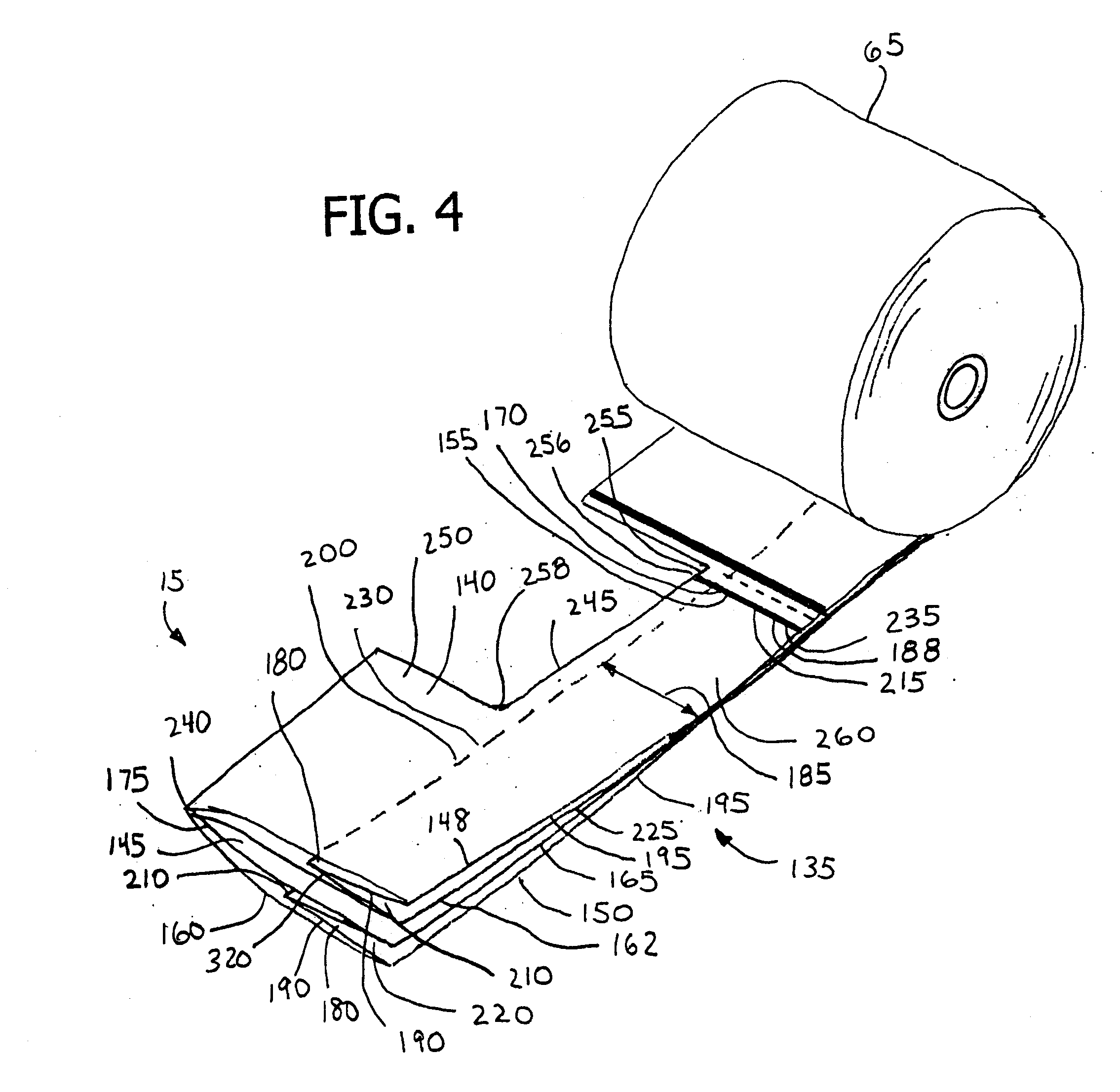
[0149]FIGS. 1-37 illustrate a combination plastic bag roll and dispenser 10 providing the desired features that may be constructed from the following components. As shown in FIGS. 4-8 and 37, a plurality of plastic bags 15 is provided. As illustrated in FIGS. 7, 8 and 37, each of the bags 15 has first 20 and second 25 parallel linear side edges, a top edge 30 and a bottom edge 35. The bags 15 are joined along a perforated severance line 40 between the bottom edge 35 of a first bag 50 and the top edge 30 of a subsequent bag 58. The bags 15 are folded along at least one axis 60 parallel to the first 20 and second 25 parallel linear side edges. The bags 15 are rolled about a horizontal axis 75 to form a compact bag roll 65 from which the bags 15 are dispensed. The compact bag roll 65 has a first predetermined width 80.

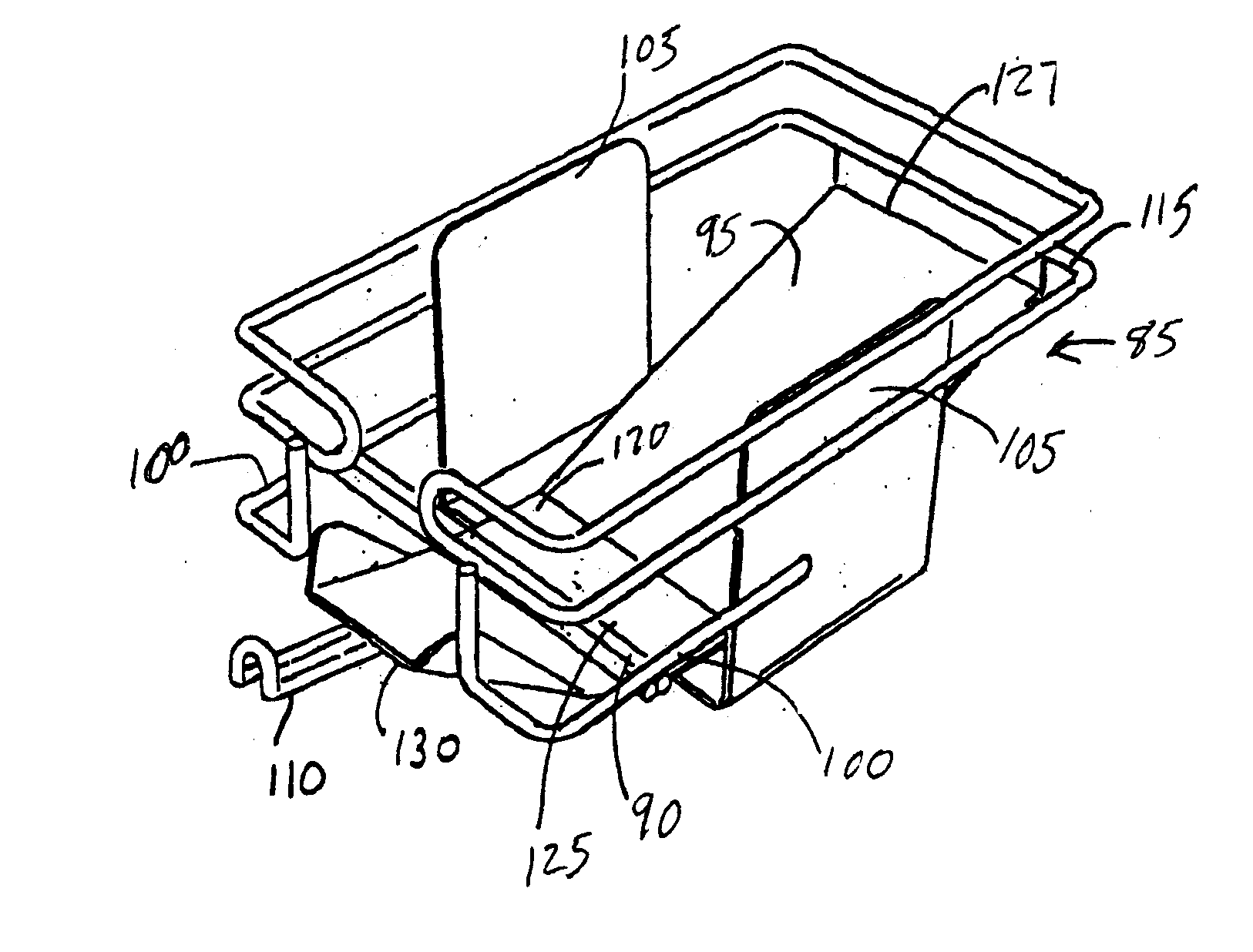
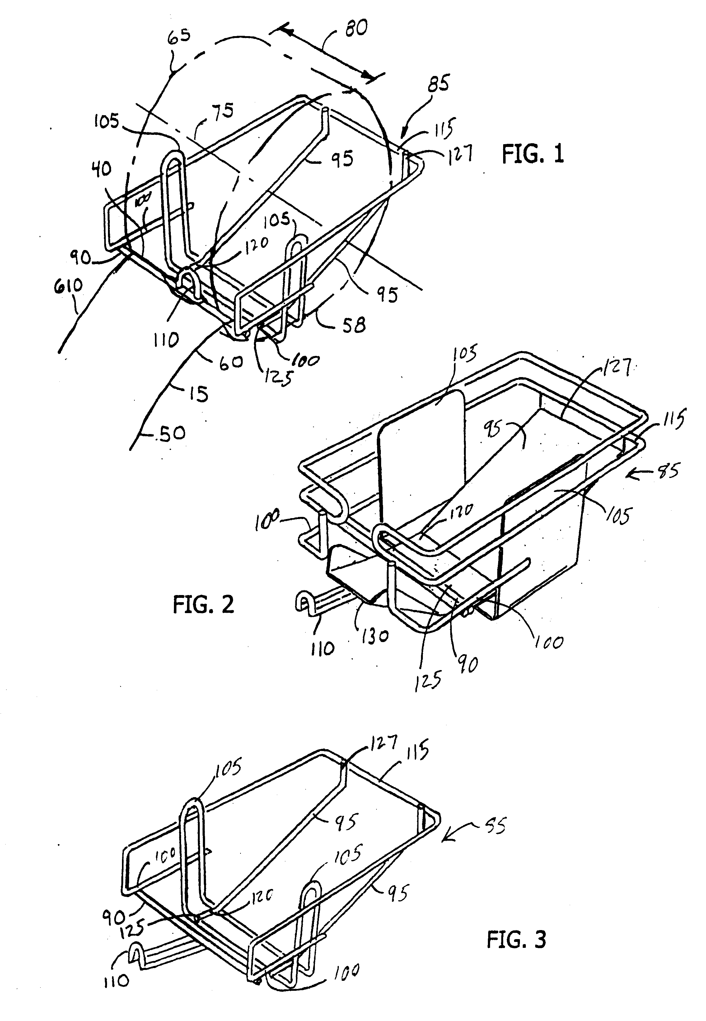
[0150] As shown in FIG. 1, a dispenser 85 is provided. The dispenser 85 includes a bag roll restraining means 90. The restraining means 90 extends across at least a port...


PUM


Abstract

A series of roll mounted bags and dispensers are described. The bags may be folded along at least one axis and rolled. The compact roll of bags is placed in various dispensers. As the upper portion of the first bag is pulled from the roll, the roll will rotate, presenting the succeeding bag for dispensing after the first bag is removed. Variations of the dispenser include one with a bag opening means with a mounting member and bag opening element causing the bags to open as they are pulled from the dispenser. The dispenser includes mechanisms for supporting the bag roll and constraining its movement along its horizontal axis. Another variation of the dispenser has a perforation parting means that facilitates separation of one bag from a subsequent bag. The dispenser may be removably attached to a dispenser support that attaches to a surface.

Description

[0001] This is a Divisional Application of U.S. application Ser. No. 10 / 193,974, filed Jul. 12, 2002.FIELD OF INVENTION [0002] The invention pertains to plastic bags and means for storing and dispensing such bags. More particularly, the invention relates to expandable plastic film bags designed for roll dispensing. BACKGROUND OF THE INVENTION [0003] Plastic bags are commonly used in supermarkets, department stores and similar applications. These bags have advantages in that they are relatively inexpensive to produce, provide substantial carrying capacity and may include easily used handles. The bags may be dispensed from flat packs or from dispensers for bags wound on rolls. Several problems are typically encountered when thin, flexible bags are used for bagging fresh produce and similar items. [0004] Thin plastic bags tend to stick together and the mouths of the bags tend to be difficult to open. When the bags are dispensed from flat packs, they can easily become disordered and oft...

Claims


Application Information

Patent Timeline
Patent Type & Authority Applications(United States)
IPC IPC(8): B26F3/02A47F9/04B65DB65D33/00B65H35/10
CPCA47F9/042A47F2009/044B65H2701/191B65D33/002B65H35/10B26F3/02Y10T225/30Y10T225/294Y10T225/321Y10T225/252Y10T225/393
Inventor DANIELS, MARK E.
Owner DANIELS MARK E
Why Eureka
Try Eureka