Eureka AIR delivers breakthrough ideas for toughest innovation challenges, trusted by R&D personnel around the world.

X-ray CT apparatus

a computed tomography and x-ray technology, applied in the field of x-ray ct (computed tomography) image acquisition method, can solve the problems of high possibility of excessive dose of x-ray applied to the subject, inability of the operator to correctly grasp the value of x-ray dose exposure of the subject, and high exposure of the subj

Inactive Publication Date: 2007-03-08
GE MEDICAL SYST GLOBAL TECH CO LLC
View PDF15 Cites 31 Cited by
  • Summary
  • Abstract
  • Description
  • Claims
  • Application Information

AI Technical Summary

Benefits of technology

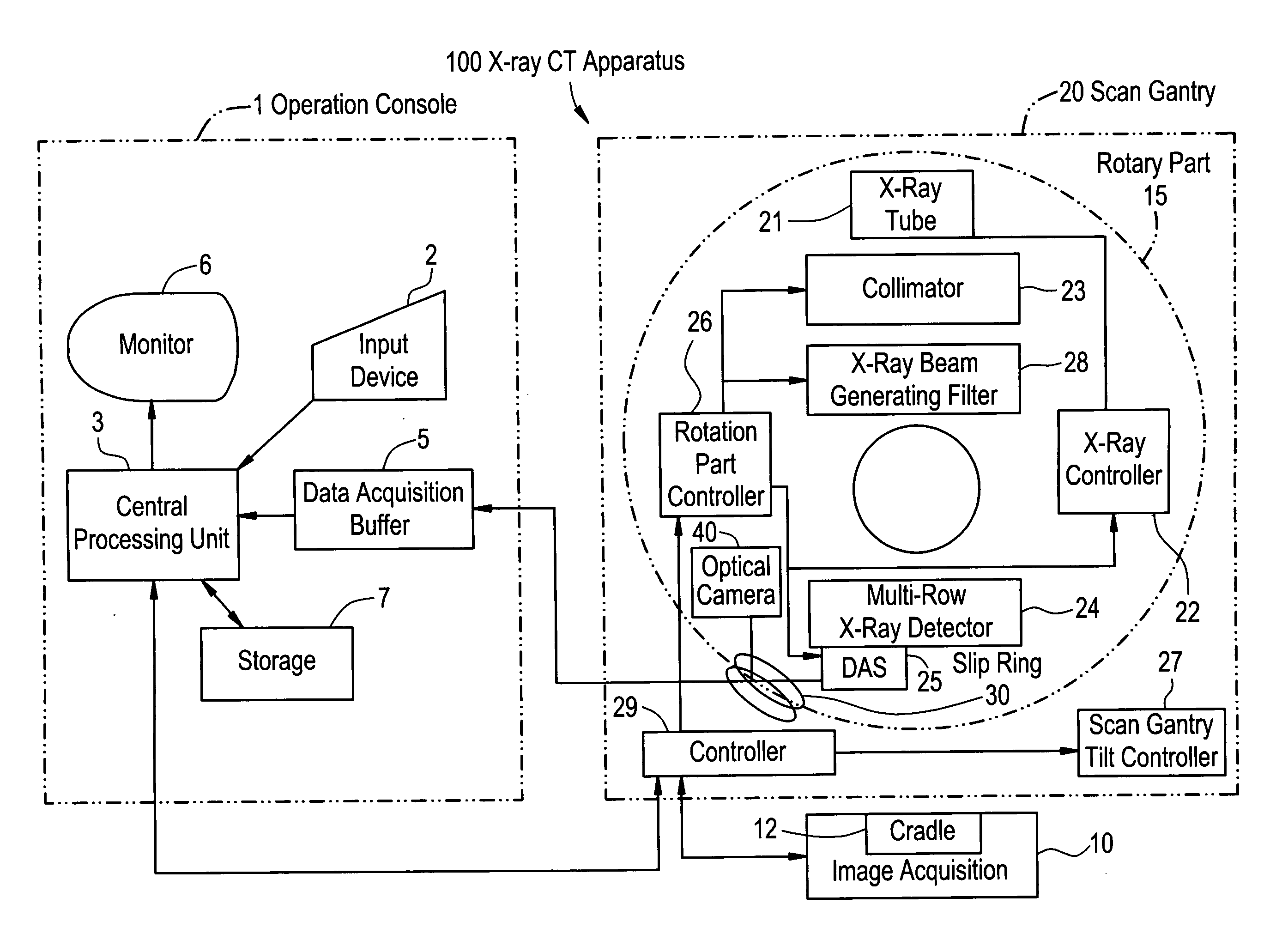
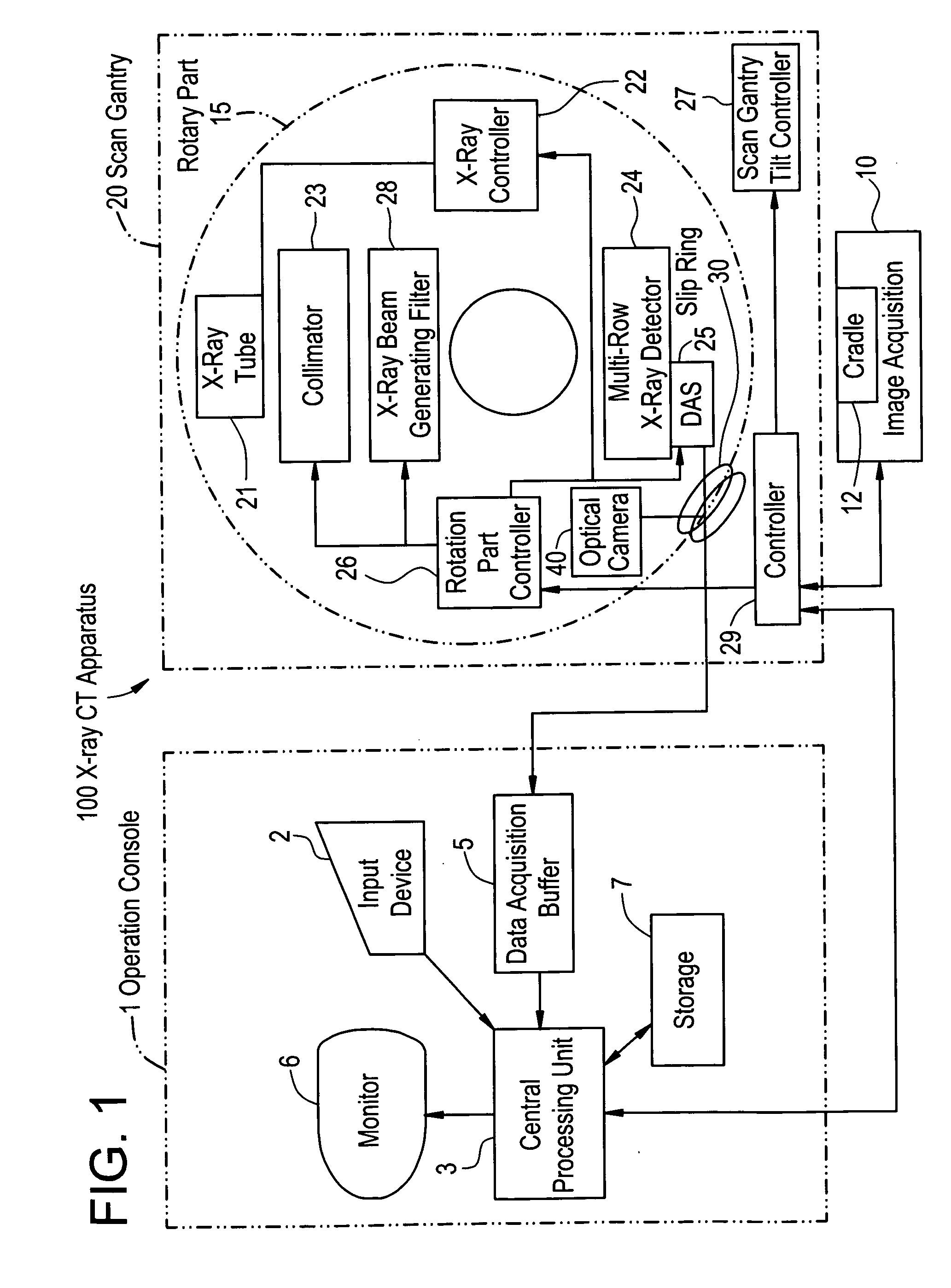
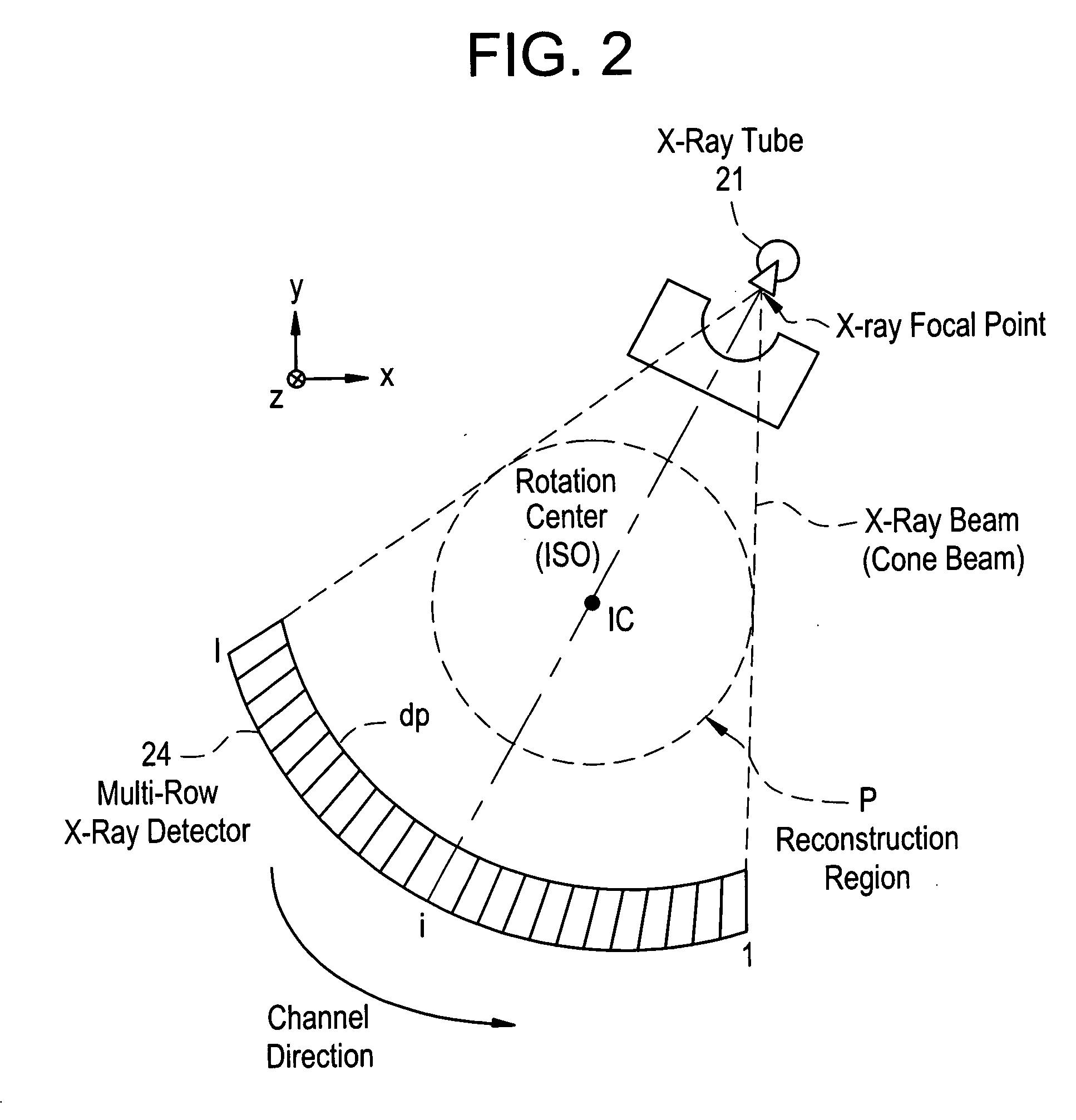
[0044] According to the X-ray CT apparatus or the X-ray CT image reconstructing method of the present invention, the X-ray CT apparatus capable of providing more-accurate X-ray dose information based on the size of a subject and more-accurate X-ray dose information in finer unit for each region of interest in a subject which is set at the time of setting image acquisition parameters in a conventional scan (axial scan), a cine scan, a helical scan, or a variable-pitch helical scan of an X-ray CT apparatus having a multi-row X-ray detector or a two-dimensional area sensor of a matrix structure typified by a flat panel X-ray detector can be realized.

Problems solved by technology

The conventional method has the problem from the viewpoint of directly displaying X-ray dose information of only the region of interest.
Since a DLP (Dose Length Product) value is an integrated value in the z direction of the CTDI values, there are problems similar to the above.
As described above, the CTDI value and the DLP value are not influenced by the size of a subject and are not proportional to the field of view of image acquisition, so that the operator cannot correctly grasp a value of X-ray dose exposure of the subject.
Due to this, there is the possibility that exposure of the subject becomes excessive if X-ray dose information such as a CTDI value and a DLP value is not correctly displayed, and this is a problem from the viewpoint of X-ray exposure.
In the case where the operator tries to have higher picture quality of a thin tomographic image, the possibility that a dose of an X-ray applied to the subject tends to be excessive is high.

Method used


Image

  • X-ray CT apparatus
  • X-ray CT apparatus
  • X-ray CT apparatus

Examples


example 1

[0150] When the embodiment is applied to an actual helical scan, X-ray dose information of the whole region of image acquisition, X-ray does information of a region 1 of interest (heart), and X-ray dose information of a region 2 of interest (liver) is known. In view of sensitivity to X-ray exposure of each of the organs, reduction in the exposure of the subject can be considered.

[0151] Also in a conventional scan (axial scan) or a cine scan, similarly, each of the X-ray dose information of the whole region of image acquisition and X-ray dose information of the region 1 of interest is known as shown in FIG. 28, so that the X-ray exposure of each of the organs and the X-ray exposure of the whole region can be taken into consideration.

example 2

[0152] In Example 2, the case of a variable-pitch helical scan as shown in FIG. 29 will be described. In the variable-pitch helical scan, as shown in FIG. 29, the helical pitch and noise index (index value of image noise) vary in the z-direction range, for example, in the heart, liver, and lung field. Consequently, the X-ray dose information in the positions in the z-direction is not easily known at a glance in comparison with a normal conventional scan (axial scan), a cine scan, or a helical scan, so that it is even more necessary to display the X-ray dose information. In this case as well, by displaying the X-ray dose information with respect to each of the whole region, the region 1 of interest (heart), the region 2 of interest (lung field), and the region 3 of field (liver), the information is shown more clearly to the operator. Therefore, reduction in the exposure of the subject can be considered in view of the sensitivity to X-ray exposure of each of the organs.

example 3

[0153] In Example 3, an X-ray profile area Sx obtained from a scout view is used to obtain the correlation with a water substitute phantom to be referred to. Height, weight, age, an image acquisition region, and sex are investigated statistically. As shown in FIG. 30A, the relations among weight, height, and sectional area of a region are obtained with respect to each of sex, the range of ages, and regions, and a regression plane or regression curve is derived from distributed statistic data. Alternately, as shown in FIG. 30B, the relations among the weight, height, and sectional area of a water substitute phantom are obtained, and a regression plane or regression curve is derived from distributed statistic data. An expression of the regression plane or regression curve is also obtained.

[0154] When sex, age, a region, weight, and height are entered, the sectional area of the region and the sectional area of a water substitute phantom are obtained by the expression of the regression...


PUM

PropertyMeasurementUnit
angleaaaaaaaaaa
heightaaaaaaaaaa
weightaaaaaaaaaa

Abstract

This invention provides an X-ray CT capable of presenting information of exposure to the operator by displaying X-ray dose information of each of regions of interest to be scanned by an X-ray CT apparatus, thereby encouraging reduction in exposure and optimization. X-ray dose information of each region to be scanned by a conventional scan (axial scan), a cine scan, a helical scan, or a variable-pitch helical scan of an X-ray CT apparatus is displayed so that the operator can recognize the X-ray dose information before acquisition of an image of a subject. The X-ray dose information can be predicated with higher precision and displayed by using a dose prediction value obtained by an interpolation value and an extrapolation value of the first or higher order on at least three or more kinds of phantom measurement values, not a simple prediction value such as a zero-th order interpolation value or a zero-th order extrapolation value obtained by using measurement values of two kinds of phantoms like in the present CTDI display.

Description

CROSS REFERENCE TO RELATED APPLICATIONS [0001] This application claims the benefit of Japanese Application No. 2005-244107 filed Aug. 25, 2005. BACKGROUND OF THE INVENTION [0002] The present invention relates to an X-ray CT (Computed Tomography) image acquiring method using an X-ray CT apparatus for medical or industrial use, and to an X-ray CT apparatus. More particularly, the invention relates to a display method of displaying X-ray dose information of each region of interest in a conventional scan (axial scan in other word), a cine scan, a helical scan, or a variable-pitch helical scan to an operator, thereby encouraging reduction in exposure and optimization. [0003] Conventionally, in an X-ray CT apparatus using a multi-row X-ray detector or an X-ray CT apparatus using a matrix structure two-dimensional X-ray area detector typified by a flat panel, in the case of acquiring images from the neck to the liver or from the lung field to the liver by a helical scan as shown in FIG. 12...

Claims


Application Information

Patent Timeline
Patent Type & Authority Applications(United States)
IPC IPC(8): H05G1/60A61B6/00G01N23/00G21K1/12
CPCA61B6/00A61B6/032A61B6/542G01N2223/612A61B6/027A61B6/583G01N2223/419G01N23/046G01N2223/1016
Inventor NISHIDE, AKIHIKOHORIUCHI, TETSUYAIMAI, YASUHIRO
Owner GE MEDICAL SYST GLOBAL TECH CO LLC
Why Eureka
Eureka Blog
Learn More