Spine distraction implant and method

a technology of implant and dislocation, applied in the field of spinal dislocation implant and method, can solve the problem of being small when compared to other devices and methods, and achieve the effect of reducing trauma, increasing space, and being easily and conveniently secured

Inactive Publication Date: 2007-03-08
KYPHON
View PDF99 Cites 192 Cited by
  • Summary
  • Abstract
  • Description
  • Claims
  • Application Information

AI Technical Summary

Benefits of technology

[0011] In order to assist in the fusing process, the supplemental spinal fixation device and method of the invention immobilizes the vertebral bodies by immobilizing the respective spinous processes extending therefrom. In addition, the present invention and method can be used to distract apart the posterior sides of the vertebral bodies in order to put additional force and compression on the anterior sides of the vertebral bodies, further assisting in the interbody fusion process.
[0034] In still a further aspect of the invention, the spacer is egg-shaped in order to accommodate the shape of the spinous process and the space there between. In a further aspect of the invention, in particular with respect to the egg-shaped spacer, the spacer has a bore there through on which the spacer can rotate, which bore is offset, being closer to the blunt end of the shape spacer than the pointed end. This allows the spacer to have the pointed end positioned closer to the spine. According, more surface area of the spacer supports the spinous processes in areas where the spinous processes are stronger.

Problems solved by technology

However, these are minimal when compared to other devices and methods.

Method used


Image

  • Spine distraction implant and method
  • Spine distraction implant and method
  • Spine distraction implant and method

Examples


first embodiment

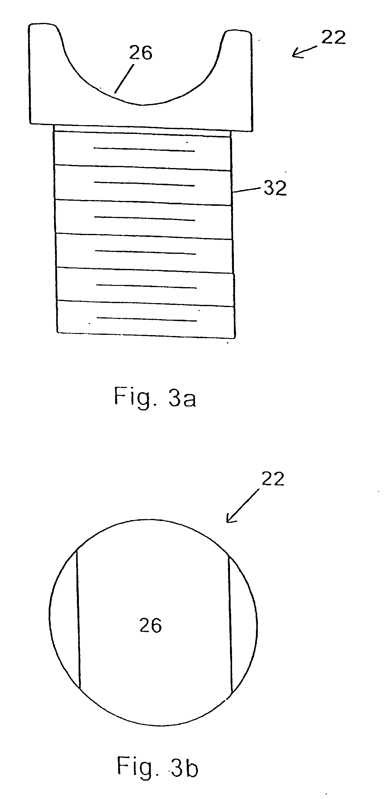
[0128] the invention is shown in FIGS. 1-5a, 5b. Implant 20 includes first and second forked ends 22 and 24, each defining a saddle 26, 28 respectively. The forked ends 22, 24 are mated using an interbody piece 30. As can be seen in FIGS. 3a, 3b, the first forked end 22 includes a threaded shaft 32 which projects rearwardly from the saddle 26. The threaded shaft 32 fits into the threaded bore 34 (FIG. 4a) of the interbody piece 30.

[0129] The second forked end 24 (FIGS. 5a, 5b) includes a smooth cylindrical shaft 36 which can fit into the smooth bore 38 of the interbody piece 30.

[0130]FIG. 1 shows the implant 20 in a fully extended position, while FIG. 2 shows the implant in an unextended position. In the unextended position, it can be seen that the threaded shaft 32 of the first forked end 22 fits inside the hollow cylindrical shaft 36 of the second forked end 24.

[0131] For purposes of implantation between adjacent first and second spinous processes of the spinal column, the impla...

embodiment 110

[0144] The embodiment of implant 130 is not circular in overall outside appearance, as is the embodiment 110 of FIGS. 14 and 15. In particular, with respect to the embodiment of implant 130 of FIGS. 16 and 17, this embodiment is truncated so that the lateral side 140, 142 are flattened with the upper and lower sides 144, 146 being elongated in order to capture and create a saddle for the upper and lower spinous processes. The upper and lower sides, 144, 146 are rounded to provide a more anatomical implant which is compatible with the spinous processes.

[0145] If it is desired, and in order to assure that the first member 132 and the second member 134 are aligned, key 148 and keyway 150 are designed to mate in a particular manner. Key 148 includes at least one flattened surface, such as flattened surface 152, which mates to an appropriately flattened surface 154 of the keyway 150. In this manner, the first member is appropriately mated to the second member in order to form appropriate...

embodiment

of FIG. 44

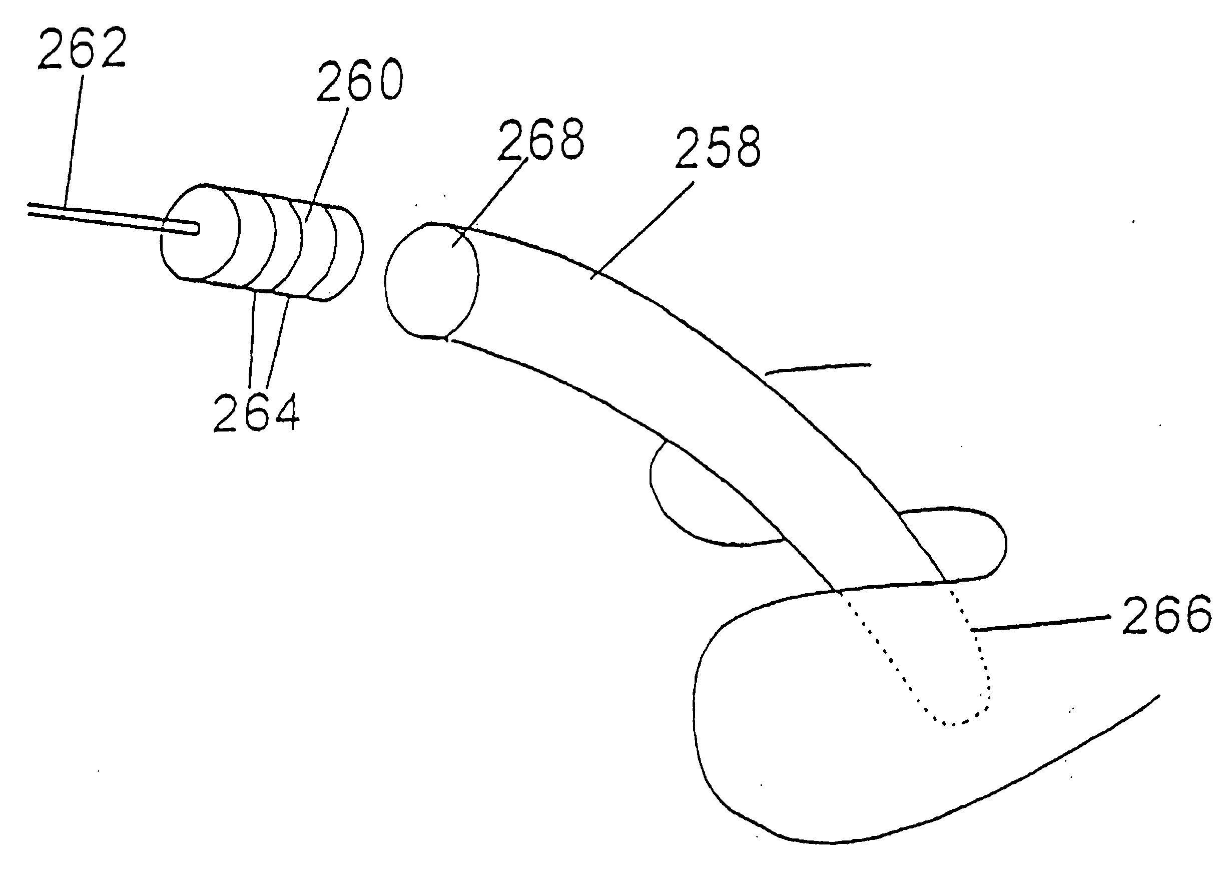
[0169] A further embodiment of the invention is shown in FIG. 44. This embodiment includes a combination insertion tool and implant 290. The insertion tool and implant 290 is in the shape of a ring which is hinged at point 292. The ring is formed by a first elongated and conically shaped member 294 and a second elongated and conically shaped member 296. Members 294 and 296 terminate in points and through the use of hinge 292 are aligned and meet. Through similar incisions on both sides of the spinous processes, first member and second member are inserted through the skins of the patient and are mated together between the spinous processes. After this has occurred, the implant 290 is rotated, for example clockwise, so that increasingly widening portions of the first member 292 are used to distract the first and second spinous processes. When the appropriate level of distraction has occurred, the remainder of the ring before and after the section which is located between the...


PUM

PropertyMeasurementUnit
heightaaaaaaaaaa
heightaaaaaaaaaa
angleaaaaaaaaaa

Abstract

A supplemental spine fixation device and method is used in association with a primary spine fixation device. The supplemental spine fixation device includes a guide and spacer for distracting apart adjacent spinous processes and the device has hook members which hook about the first and second spinous processes. With the spinous processes distracted and the hook members about the spinous processes, the hook members can be rigidly secured to a hub in order to rigidly affix the spinous processes about the spacer. The rigidity between the spinous processes assures that the vertebral bodies will be held rigidly in place in order to promote bone growth and fusion. Further additional freedom of movement between the spacer and hub is accomplished with the spacer being pivotably mounted relative to the hub. The hooks have a tissue distracting lead-in guide for allowing the hooks to be easily urged between spinous processes.

Description

CLAIM OF PRIORITY [0001] This application is a continuation of U.S. patent application Ser. No. 09 / 842,819, filed Apr. 26, 2001, entitled SUPPLEMENTAL SPINE FIXATION DEVICE AND METHODS, which claims priority from U.S. Provisional Patent Application No. 60 / 219,985, filed Jul. 21, 2000, and is a continuation-in-part of U.S. patent application Ser. No. 09 / 579,039, filed May 26, 2000, now U.S. Pat. No. 6,451,019, entitled SUPPLEMENTAL SPINE FIXATION DEVICE AND METHOD, which is a continuation-in-part of U.S. patent application Ser. No. 09 / 473,173, filed Dec. 28, 1999, now U.S. Pat. No. 6,235,030, entitled SPINE DISTRACTION IMPLANT, which is a continuation of U.S. patent application Ser. No. 09 / 179,570, filed Oct. 27, 1998, now U.S. Pat. No. 6,048,342, entitled SPINE DISTRACTION IMPLANT, which is a continuation-in-part of U.S. patent application Ser. No. 09 / 175,645, filed Oct. 20, 1998, now U.S. Pat. No. 6,068,630, entitled SPINE DISTRACTION IMPLANT, which is a continuation-in-part of U.S...

Claims


Application Information

Patent Timeline
Patent Type & Authority Applications(United States)
IPC IPC(8): A61F2/30A61B17/66A61B17/70A61B17/88A61K31/37
CPCA61B17/66A61B17/7047A61K31/37A61B17/7068A61B17/7071A61B17/7065
Inventor ZUCHERMAN, JAMES F.HSU, KEN Y.FALLIN, T. WADEKLYCE, HENRY A.
Owner KYPHON
Why Eureka
Try Eureka