Connection devices

a technology of connecting devices and guide wires, which is applied in the direction of movable seats, couplings, transportation and packaging, etc., can solve the problem that the projected dowels used to attach the guide wires to the frame portion of the seat back cannot be substantially formed in positions closer to an outer circumferential periphery of the guide wire, and achieves the effect of increasing the connection strength and compact arrangemen

Active Publication Date: 2012-09-11
TOYOTA BOSHOKU KK
View PDF28 Cites 28 Cited by
  • Summary
  • Abstract
  • Description
  • Claims
  • Application Information

AI Technical Summary

Benefits of technology

[0009]According to the structure of the present invention, the axially extending retainer strips of the retainer member are axially inserted into the depressed portions formed in the outer circumferential portion of one of the connecting elements and then are bent, so that the bent formed contact surface portions thereof can be axially held against one of the connecting elements. As a result, the retainer member can prevent one of the connecting elements from being disengaged. Thus, because the retainer member can be attached to one of the connecting elements without radially projecting from the outer circumferential portion of one of the connecting elements, the connecting device can be downsized. Further, because the axially projected fitting portions formed in one of the connecting elements are formed circumferentially in the locations positioned between the depressed portions, the fitting portions cannot interfere with the above-described bent ends (the contact surface portions) of the retainer member. As a result, the fitting portions can be positioned closer to an outer circumferential periphery of one of the connecting elements. Therefore, even when the connecting device is downsized, a connection strength between one of the connecting elements and one of the subject components can be ensured.
[0011]According to the structure of the present invention, because the fitting portions are positioned outside of the outwardly-faced toothed surface formed in one of the connecting elements, the fitting portions are positioned closer to the outer circumferential periphery. Therefore, the connection strength between one of the connecting elements and one of the subject components via the fitting portions can be increased.
[0013]According to the structure of the present invention, because the projected fitting portions formed in one of the connecting elements are shaped to be extended in the circumferential direction, the fitting portions have increased shear strength in the circumferential direction. Further, the fitting portions and one of the subject components can be fitted to each other in a large area. As a result, the connection strength between one of the connecting elements and one of the subject components can be increased.
[0017]According to the structure of the present invention, the connecting device is constructed as the reclining device that is capable of connecting the seat back to the fixed body such as the seat cushion such that the tilting angle of the seat back can be adjusted. Therefore, the reclining device can be compactly arranged with the increased connecting strength.

Problems solved by technology

Therefore, projected dowels that are used to attach the guide to the frame portion of the seat back cannot substantially be formed in positions closer to an outer circumferential periphery of the guide.

Method used


Image

  • Connection devices
  • Connection devices
  • Connection devices

Examples


embodiment 1

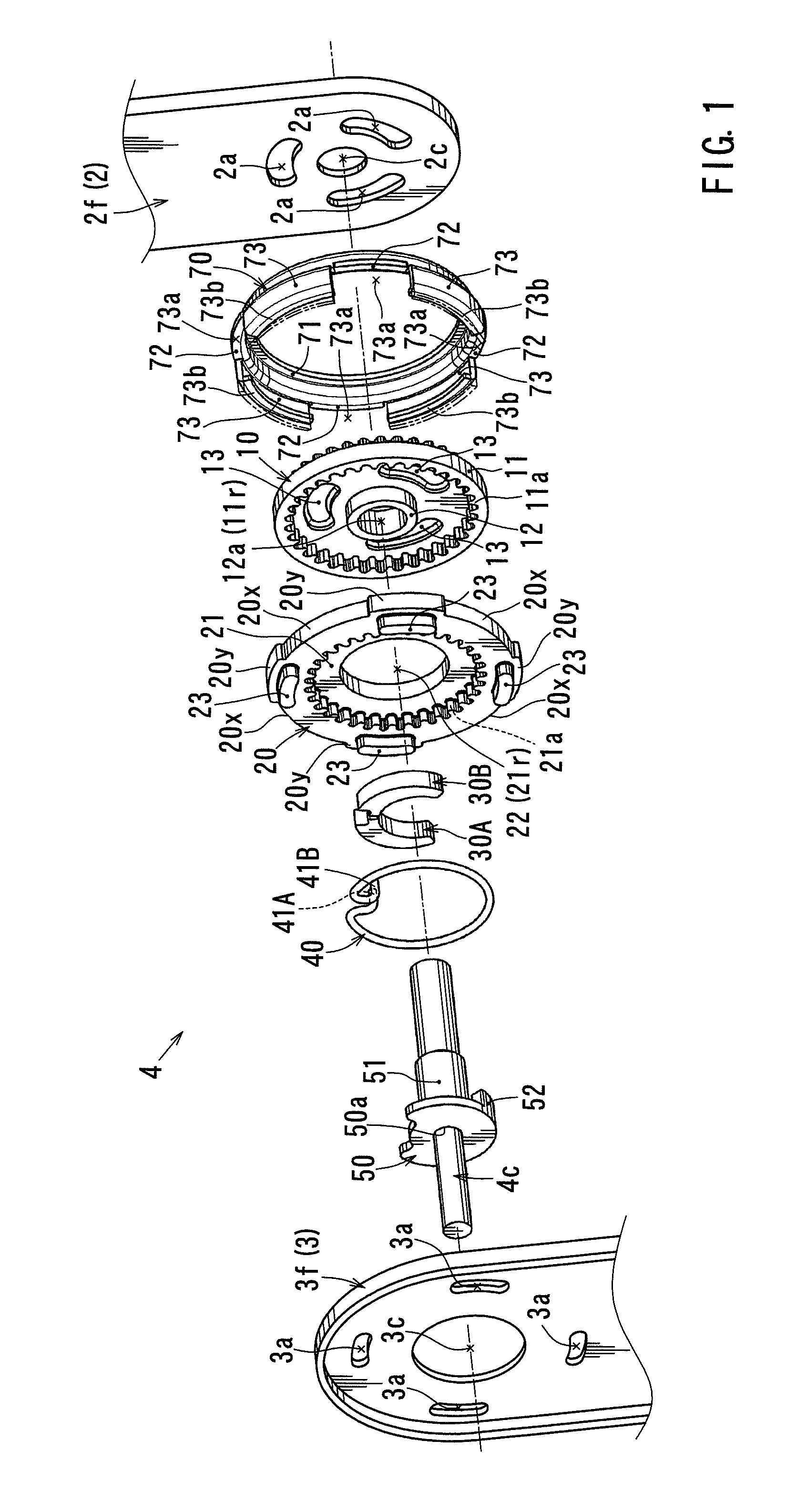
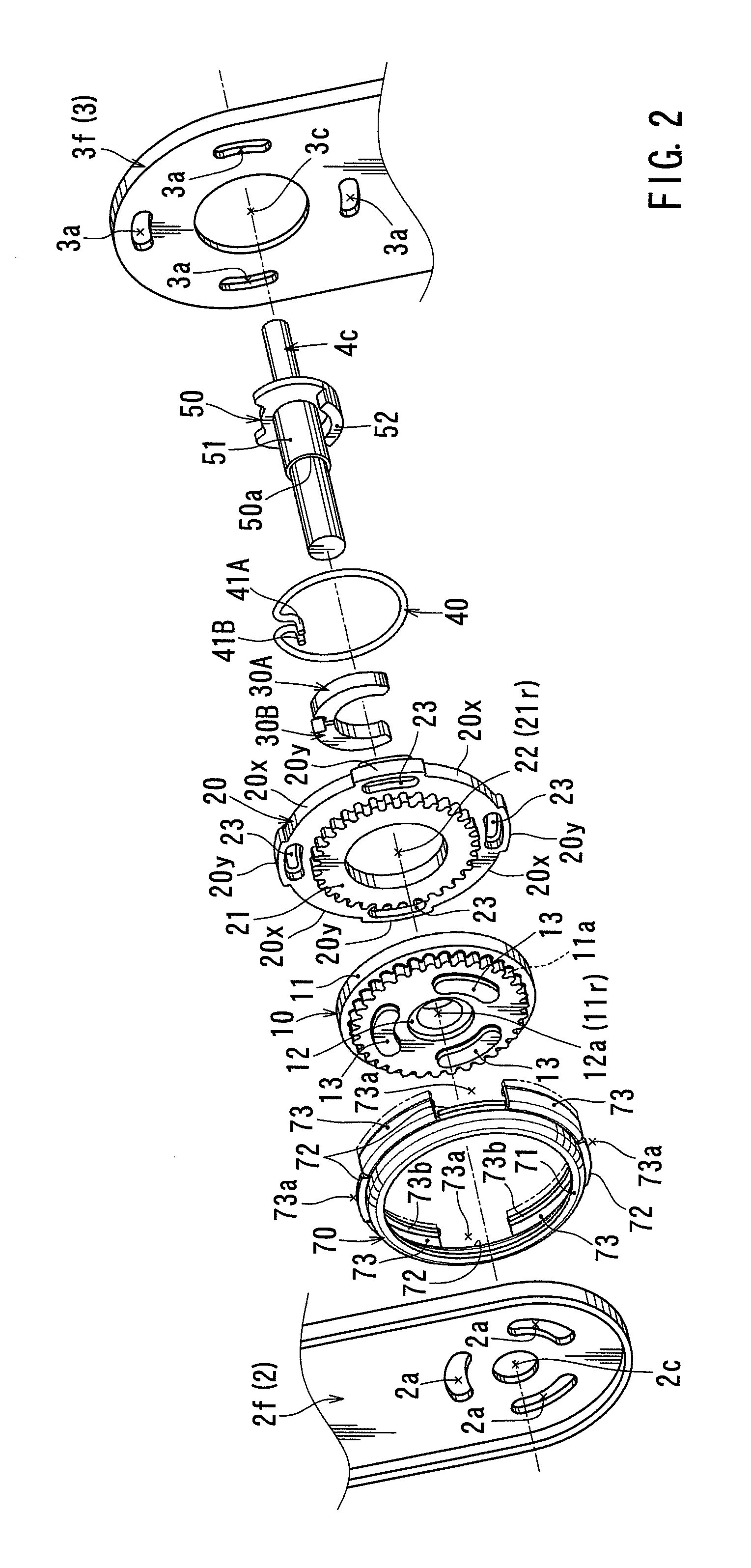
[0030]First, connecting devices of Embodiment 1 will be described with reference to FIGS. 1 to 8. FIG. 3 schematically shows a structure of a vehicle seat 1 having reclining devices 4 and 4 that correspond to connecting devices of the present invention. In the vehicle seat 1, a seat back 2 is connected to a seat cushion 3 via a pair of reclining devices 4 and 4 that are disposed on both side lower portions of the seat back 2.

[0031]Each of the reclining devices 4 and 4 is normally maintained in a condition in which a tilting angle of the seat back 2 is fixed. However, each of the reclining devices 4 and 4 is constructed to adjust the tilting angle of the seat back 2 when operating shafts 4c and 4c inserted thereinto are rotated. The operating shafts 4c and 4c are integrally connected to each other via a connection rod 4r, so as to be synchronously rotated when an electric motor (not shown) connected to one of the operating shafts 4c and 4c is actuated.

[0032]Further, the electric moto...

embodiment 2

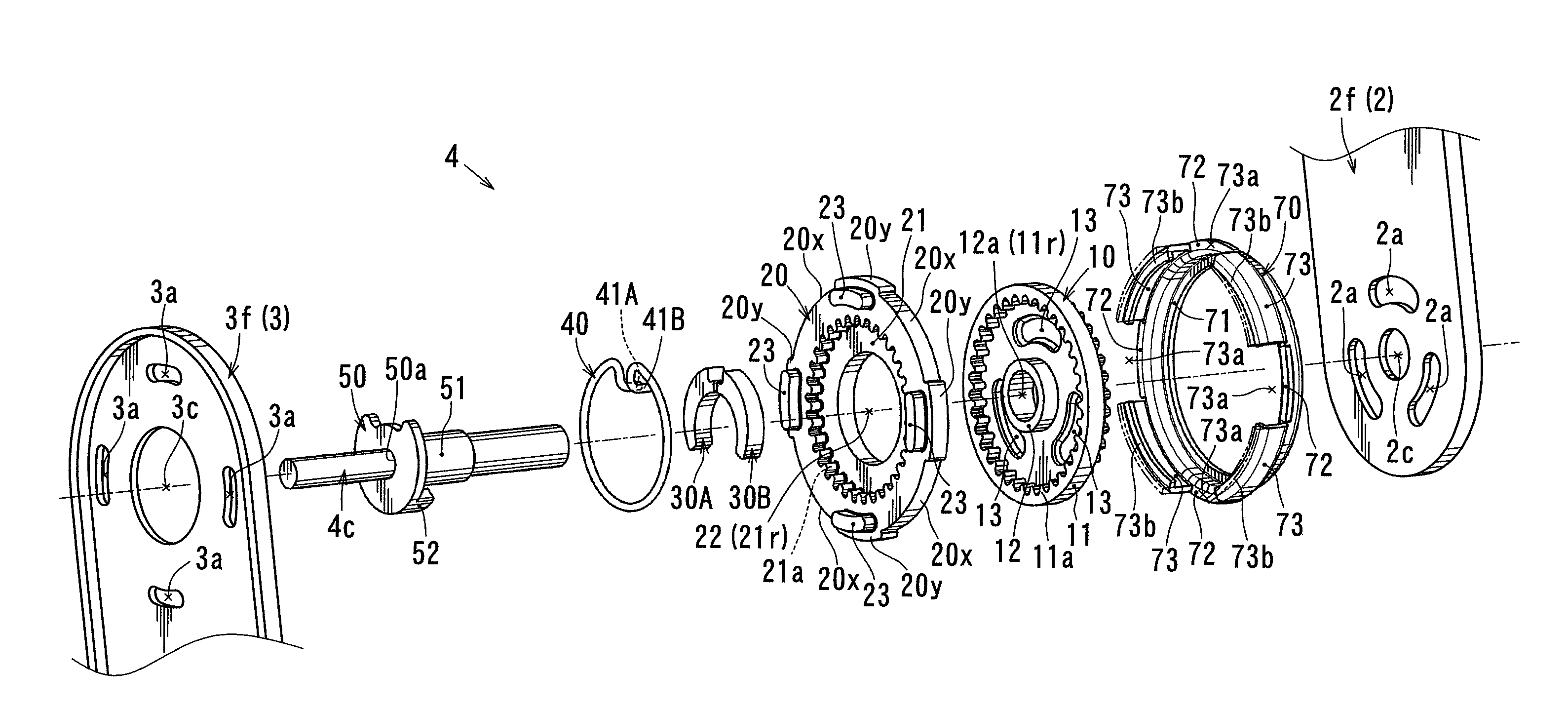
[0062]Next, a connecting device (a reclining device 104) of Embodiment 2 will be described with reference to FIGS. 9 to 11. As shown in FIG. 9, the reclining device 104 includes a disk-shaped ratchet 110, a disk-shaped guide 120, a pair of pawls 130 and 130 that are vertically disposed between disk surfaces of the ratchet 110 and the guide 120, a slide cam 140 that is disposed between the disk surfaces of the ratchet 110 and the guide 120, a hinge cam 150 that is capable of sliding the slide cam 140, a biasing spring 160 that is capable of rotatably biasing the hinge cam 150, and a retainer member 170 that is capable of fastening the ratchet 110 and the guide 120 so as to not be prevented from being axially separated from each other, which are assembled as a unit.

[0063]Further, the guide 120 corresponds to one of connecting elements of the present invention. Conversely, the ratchet 110 corresponds to the other of the connecting elements of the present invention. As shown in FIG. 9, ...


PUM


Abstract

A reclining device as a connecting device includes an internal gear member, an external gear member and a retainer member. The retainer member is constructed such that when retainer strips are axially inserted into depressed portions formed in an outer circumferential portion of the external gear member and then insertion distal ends of the support strips are radially inwardly bent to form contact surface portions, the contact surface portions can be axially held against the outer circumferential portion of the external gear member. The external gear member has dowels that are capable of being fitted to a cushion frame, and the dowels are formed circumferentially in locations positioned between the depressed portions (the locations in which projected portions are formed), so as to be axially projected.

Description

TECHNICAL FIELD[0001]The present invention relates to connection devices. More particularly, the present invention relates to connection devices for relatively rotatably connecting two subject components.BACKGROUND ART[0002]In a vehicle seat that is conventionally known, a seat back is rotatably connected to a seat cushion via a reclining device, so that a tilt angle of the seat back can be adjusted. Such a reclining device is taught by Japanese Laid-Open Patent Publication Number 2006-14942. The reclining device described therein includes a disk-shaped ratchet affixed to a frame portion of the seat back and a disk-shaped guide affixed to a frame portion of the seat cushion. The ratchet and the guide are axially assembled while being mutually supported, so as to rotate relative to each other.[0003]Also, the ratchet and the guide are circumferentially connected by a cylindrical retainer member along outer circumferential portions thereof, so as to not be axially disengaged from each ...

Claims


Application Information

Patent Timeline
Patent Type & Authority Patents(United States)
IPC IPC(8): B60N2/42
CPCB60N2/2252B60N2/2356B60N2/2254Y10T403/32418B60N2/236
Inventor MITSUHASHI, ATSUTAKA
Owner TOYOTA BOSHOKU KK
Why Eureka
Try Eureka