Front structure of all terrain vehicle

a front structure and all terrain technology, applied in the direction of jet propulsion mounting, cycle equipment, gearing, etc., can solve the problems of engine performance deterioration, adverse impact on the comfort of the rider, engine performance deterioration, etc., to achieve smooth introduction and improve cooling performance

Active Publication Date: 2008-03-25
SUZUKI MOTOR CORP
View PDF8 Cites 30 Cited by
  • Summary
  • Abstract
  • Description
  • Claims
  • Application Information

AI Technical Summary

Benefits of technology

[0008]The present invention has been achieved in view of the circumstances encountered in the prior art mentioned above, and an object of the present invention is to provide a front structure of an all terrain vehicle (ATV) capable of smoothly introducing a radiator exhaust air rearward so as to improve the cooling performance for cooling respective members of the vehicle.
[0018]According to the front structure of the all terrain vehicle of the present invention mentioned above, it becomes possible to secure the large capacity ventilation space near the rear portion of the radiator, to eliminate a member having a wide width dimension, and to create a smooth flow of the air exhausted or induced by the cooling fan. Therefore, the atmospheric temperature can be reduced, radiator cooling efficiency can be improved, and the improved cooling performance for cooling the respective members of the vehicle can be achieved.
[0019]Furthermore, the position in the vehicle body in which the engine unit is mounted can be set near the front side of the vehicle body to be closer to the radiator. In addition, the improved water proof structure can be provided so as to prevent the water or the like splashed by the front wheels from directly entering the interior of the inlet duct from the internal space in the front portion of the vehicle.

Problems solved by technology

However, if an obstacle such as the intake duct is arranged on the rear side of the radiator cooling fan, an exhaust air from a radiator induced by the cooling fan does not smoothly flow rearward, which may result in deterioration in cooling performance of the engine and an adverse impact on the comfort of the rider due to heat damage.
Furthermore, if the exhaust air from the radiator does not flow smoothly, the heat damage may be also inflicted on an engine intake system, an engine exhaust system, and the like and the engine performance may possibly be further deteriorated.
Especially, if a hot air which has passed through a radiator directly blows into an external air introducing duct for cooling the transmission, the intake air is warmed and the cooling performance to the V-belt, the seal member, and the like will be deteriorated.

Method used


Image

  • Front structure of all terrain vehicle
  • Front structure of all terrain vehicle
  • Front structure of all terrain vehicle

Examples


Embodiment Construction

[0030]A preferred embodiment of the present invention will be described hereinafter with reference to the accompanying drawings.

[0031]Further it is first to be noted that terms such as “upper”, “lower”, “right”, “left” and the like terms are used herein with reference to the illustrated state on the drawings or usual state of the vehicle on a ground.

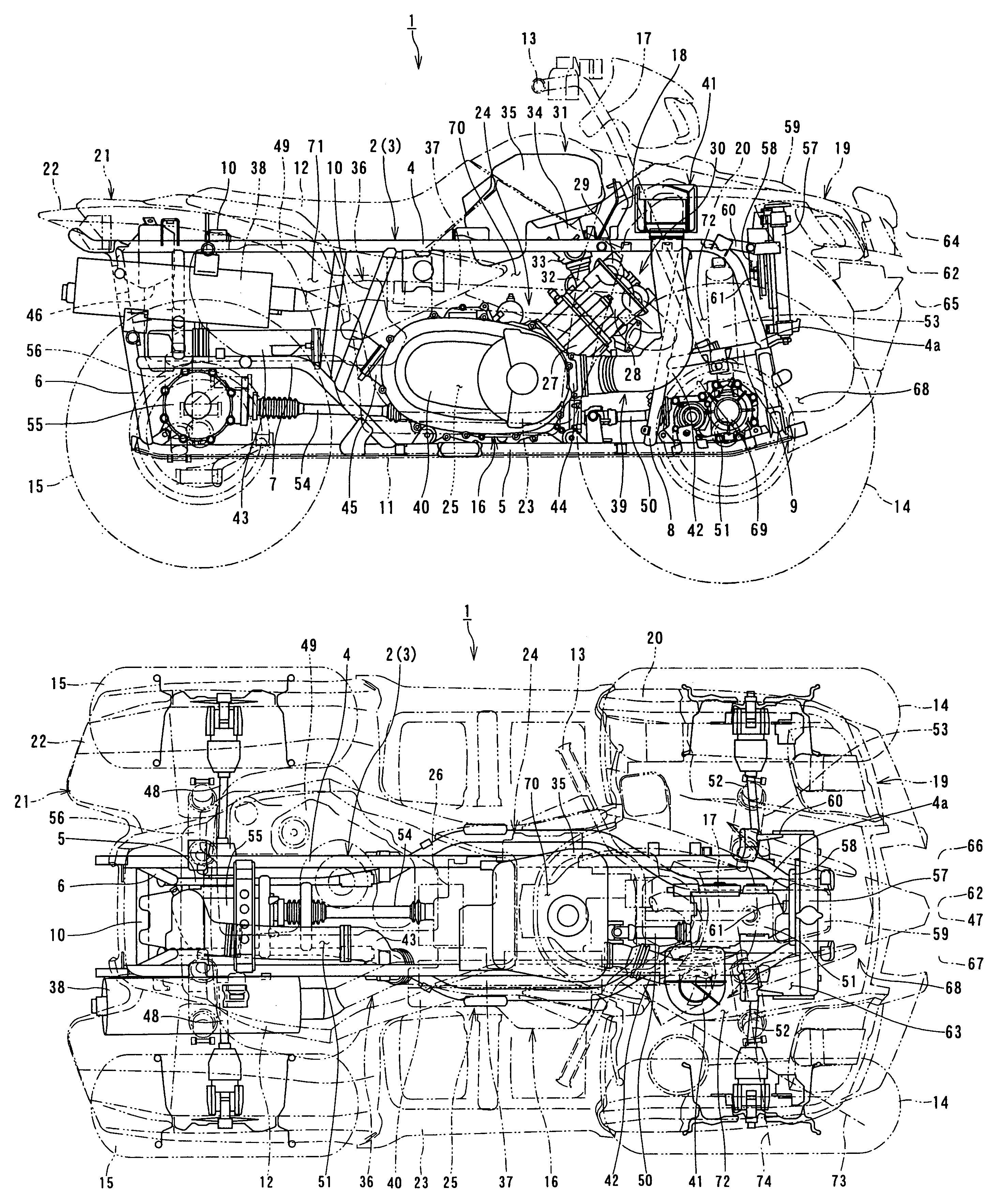
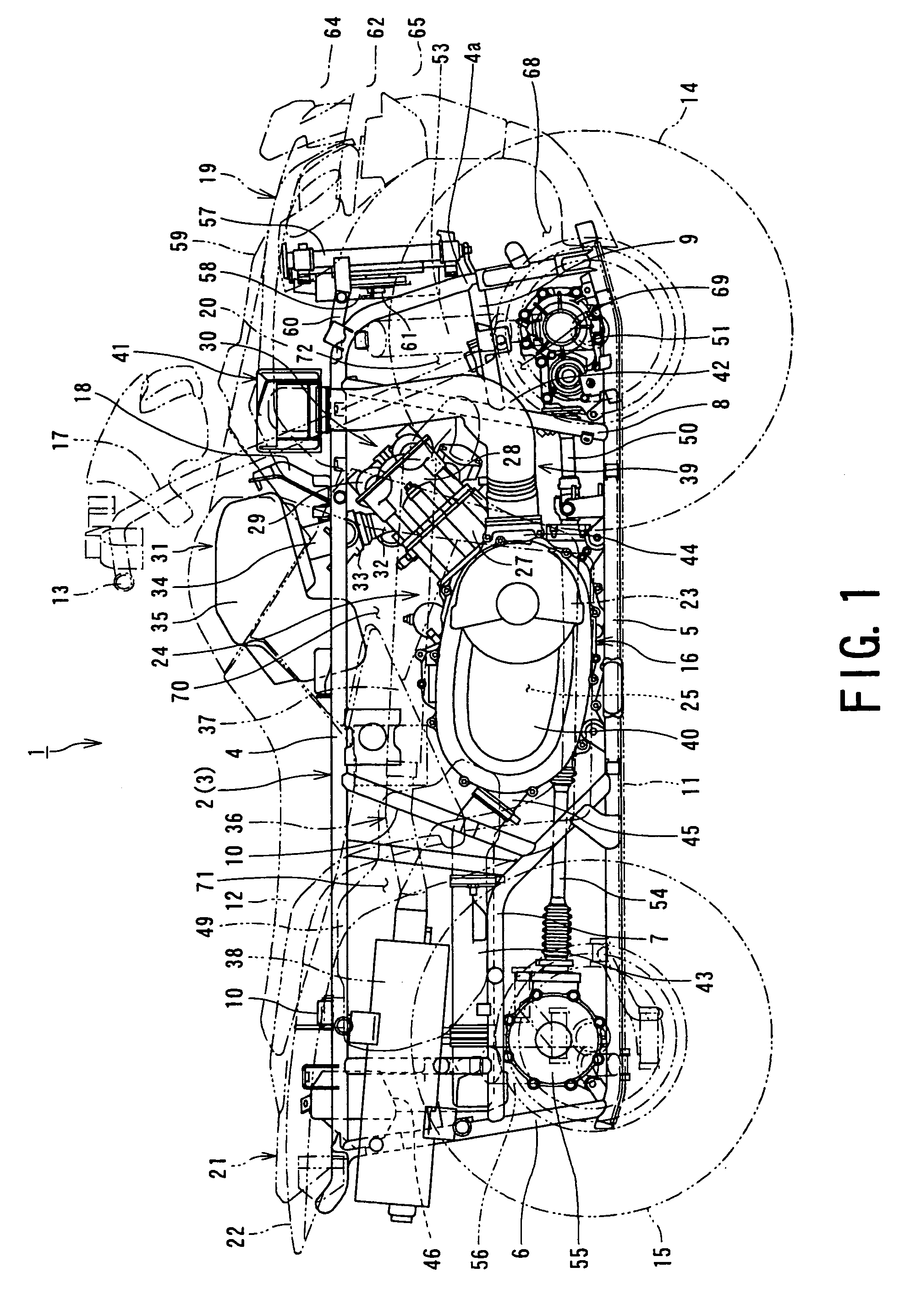
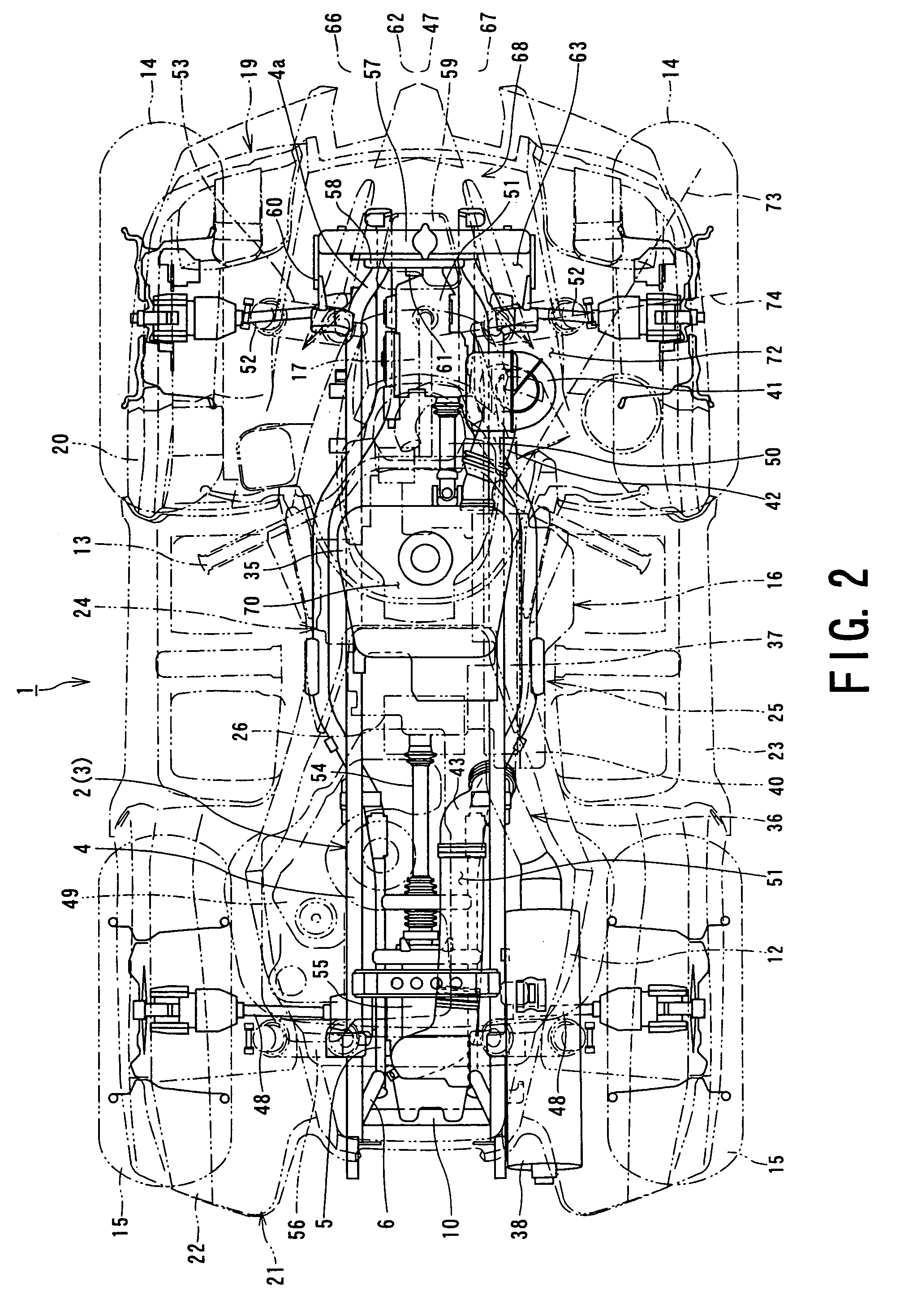
[0032]With reference to FIGS. 1 to 3, a saddle type all terrain vehicle 1 (which may be called “ATV” hereinlater), for example, such as buggy car, includes a vehicle body frame 3 formed generally into a cage shape by coupling, for example, a pair of left and right steel frame members 2. Each frame member 2 includes a pair of left and right upper frames 4 and a pair of left and right lower frames 5. A front portion of each upper frame 4 is bent downward to form a vertical frame portion 4a, and a tip end of the vertical frame portion 4a is connected to a tip end of the corresponding lower frame 5.

[0033]The frame member 2 also includes: a p...


PUM


Abstract

An all terrain vehicle for smoothly introducing an exhaust air from a radiator rearward and improving cooling performance for cooling respective members of the vehicle is provided with a front structure, in which a cooling fan is provided on a rear surface of the radiator so that a central portion of the cooling fan is offset from a center of the radiator toward a side opposite to a side on which the belt transmission is arranged, an exhaust pipe connected to a front portion of the cylinder assembly is provided to extend toward the side on which the belt transmission is arranged so that the exhaust pipe extends downward at a portion above the belt transmission, and the inlet duct is provided on the side on which the exhaust pipe is provided so as to vertically extend along the vehicle body frame provided vertically through a portion below the exhaust pipe.

Description

BACKGROUND OF THE INVENTION[0001]1. Field of the Invention[0002]The present invention relates to a front structure of an all terrain vehicle of straddle type such as buggy car.[0003]2. Description of the Related Art[0004]An engine unit, in which a belt continuously variable transmission (CVT) is provided integrally with an engine main body, and which is mounted in a saddle type all terrain vehicle (ATV) of course including a rough terrain vehicle (RTV), or a motorcycle, has a cooling structure for a vehicle transmission. The vehicle transmission cooling structure introduces, as a cooling air, a fresh air from an outside (external air) into, for example, a belt case containing the transmission through, for example, a duct to cool members within the belt case, and on the other hand, discharges the air, after cooling, into the atmosphere through, for example, a duct to thereby prevent heat generated by operation of the transmission from adversely influencing a V-belt, a seal member, et...

Claims


Application Information

Patent Timeline
Patent Type & Authority Patents(United States)
IPC IPC(8): B60K11/08B62J99/00B62K5/00B62K5/01B62K11/00B62M9/08
CPCB60K11/08B62K5/01F16H57/0415F16H57/0489B60Y2200/124F16H9/16B62J50/30
Inventor NAKAMURA, EIICHIKUSAKA, TAKUYA
Owner SUZUKI MOTOR CORP
Why Eureka
Try Eureka