Rigid handcuff

a handcuff and rigid technology, applied in the field of handcuffs, can solve the problems of placing the officer in a potentially dangerous situation, too large and cumbersome to be carried, and the rigid handcuffs are also too large and cumbersome to be conveniently carried, so as to prevent interference with the bow movement, high strength, and the effect of high strength

Inactive Publication Date: 2007-03-15
ARMAMENT SYST & PROCEDURES
View PDF11 Cites 12 Cited by
  • Summary
  • Abstract
  • Description
  • Claims
  • Application Information

AI Technical Summary

Benefits of technology

[0019] A feature of the rigid handcuff assembly of the present invention lies in providing a locking member in the connecting block that receives and mates with discrete length polygonal cross-section segments of the pivot shafts in sliding relation therewith and is spring biased to a locking position with the pivot shafts when the handcuffs are in open aligned substantially coplanar relation, but can be released from such locking position in response to relatively minimal rotation of a key inserted into the connecting block for cooperation with the locking member. The pivot shafts are preferably of high strength heat treated steel and their polygonal cross-sectional segments provide a mechanical advantage over known prior rigid handcuffs.
[0020] Another feature of the handcuff assembly of the present invention lies in hingedly connecting the bracelet type handcuffs through a connecting block as aforedescribed so that the handcuffs pivot in a direction away from a keyway provided in the connecting block and thereby prevent a handcuff from impacting the user's fingers when manipulating a key inserted into th

Problems solved by technology

This can result in placing the officer in a potentially dangerous situation.
A significant shortcoming with rigid handcuffs of the type disclosed in U.S. Pat. No. 4,840,048 is that they are too large and cumbersome to be carried with other equipment that a police officer needs to carry on his/her duty belt.
Such rigid handcuffs are also too large and cumbersome to be conveniently carried under a suit coat by detectives so as to be readily accessible but not create an identifiable bulge.
A significant drawback with the hinged handcuffs disclosed in U.S. Pat. No. 5,687,593 occurs when the hinged handcuffs are in overlying juxtaposed relation to each other, termed the closed position, as when carried on an officer's belt or the like, and the officer needs to quickly grasp the overlying handcuffs and pivot one of the handcuffs into locked aligned relation with the other, termed the open position, and grasp the rigid aligned handcuffs in proper orientation for applying the bow or clasp member of one of the handcuffs to a detainee's wrist.
This visual distraction from the detainee can often create an endangerment to the officer.
Another drawback in the commercial rigid handcuff that carries the U.S. serial number corresponding to U.S. Pat. No. 5,687,593 occurs when the officer wishes to return the handcuffs from open locked rigid aligned positions to closed compact overlying juxtaposed positions.
A further drawback in the commercial embodiment of the rigid handcuff bearing the serial number of U.S. Pat. No. 5,687,593 lies in the fact that each of the pivotally connected bracelet type handcuff members is capable of being locked in coplanar relation with the connecting member while the other handcuff member remains in its folded or closed position relative to

Method used


Image

  • Rigid handcuff
  • Rigid handcuff
  • Rigid handcuff

Examples


Embodiment Construction

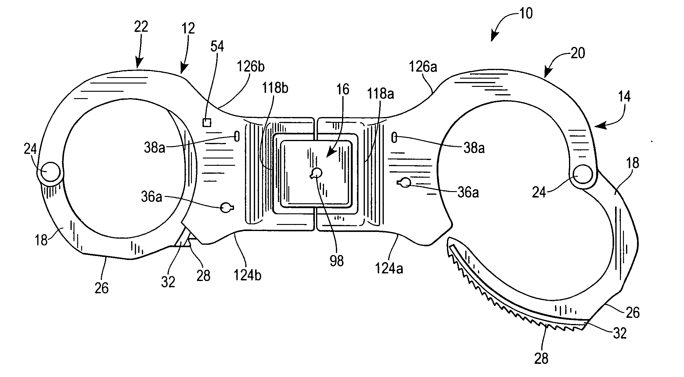
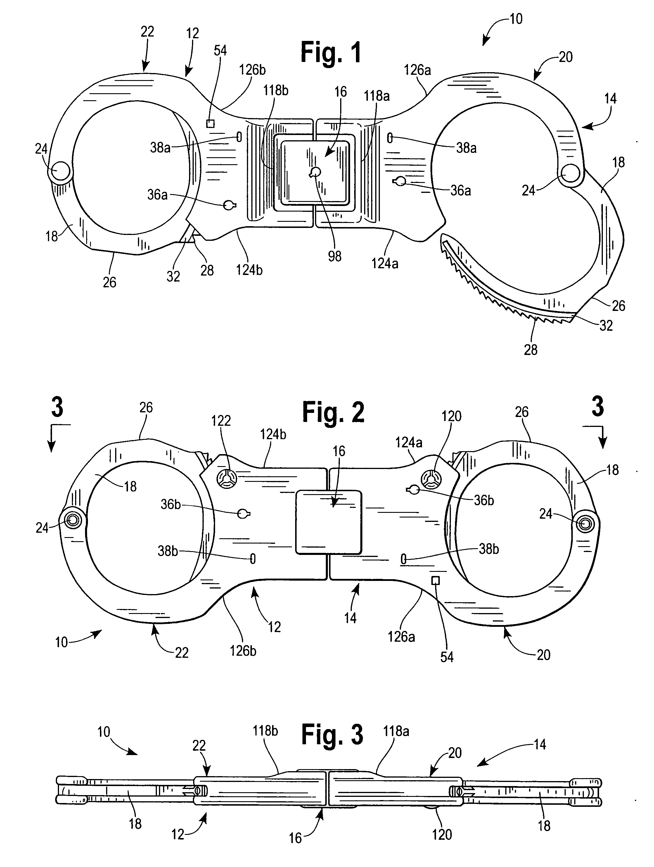
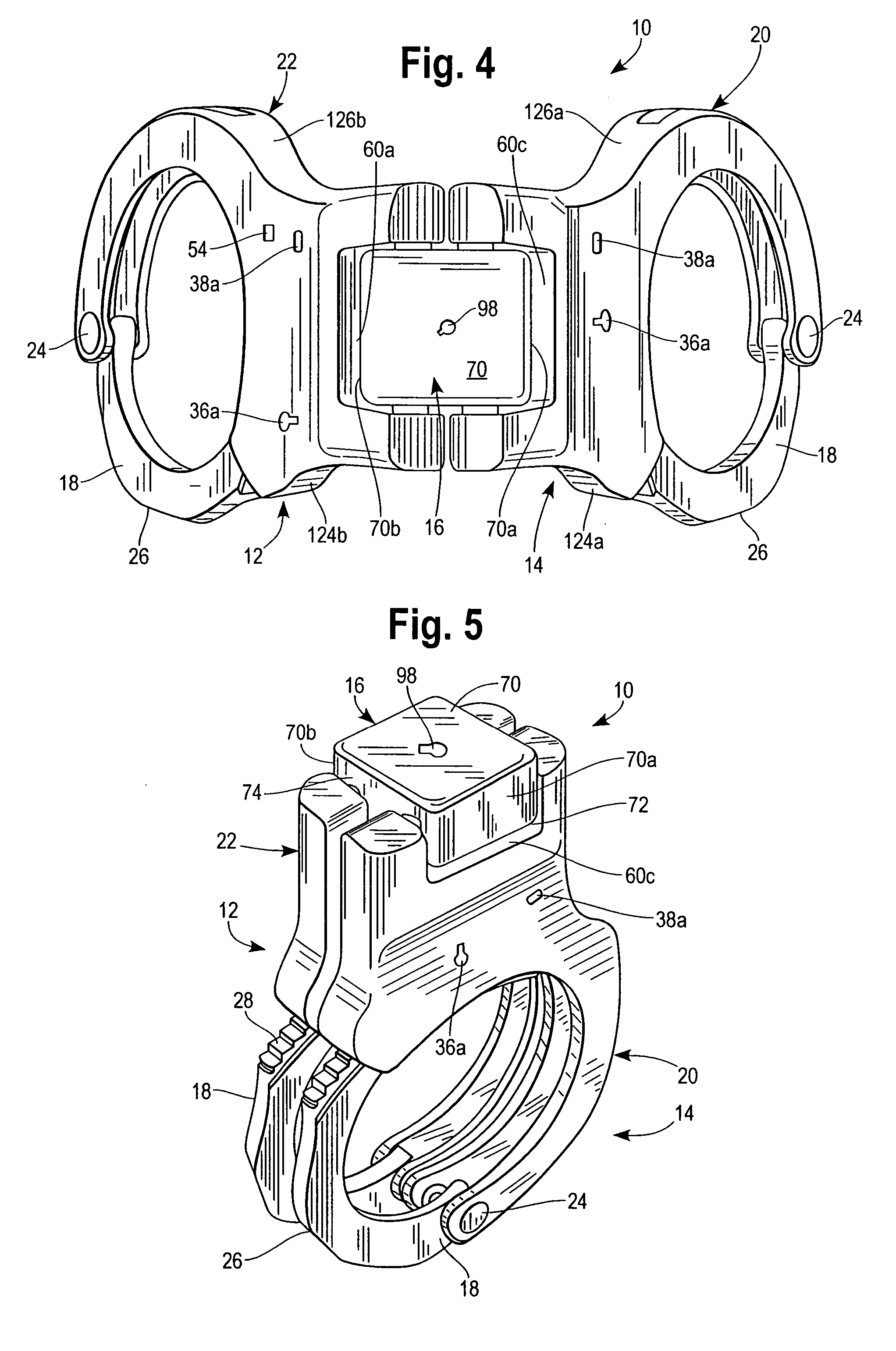
[0038] Referring now to drawings, and in particular to FIGS. 1-5, a rigid handcuff constructed in accordance with a presently preferred embodiment of the invention is indicated generally at 10. The rigid handcuff 10, which may be termed a handcuff assembly, includes a pair of bracelet type handcuffs 12 and 14 that are mirror images of each other and are pivotally or hingedly interconnected to each other through a connecting block indicated generally at 16. Very generally, the handcuffs 12 and 14 are adapted to be releasably locked in rigid aligned substantially coplanar relation, termed open positions as illustrated in FIGS. 1-3, but can be pivotally folded about pivot axes defined by the connecting block to positions wherein the handcuffs are in overlying substantially juxtaposed relation, termed closed positions as illustrated in FIG. 5.

[0039] Each of the handcuffs 12 and 14 includes an arcuately shaped bow 18 that is pivotally connected to a cheek plate assembly 20 that may be m...


PUM


Abstract

A rigid handcuff assembly is disclosed that includes a pair of handcuff bracelets adapted to be releasably applied to a person's wrists. The handcuff bracelets include cheek plate assemblies that are pivotally interconnected to a connecting block that includes locking mechanism enabling movement of the handcuff bracelets between folded positions disposed in overlying juxtaposed relation, and positions wherein the handcuffs are automatically locked in rigid substantially coplanar aligned relation. The interconnected cheek plate assemblies define a handgrip when disposed in rigid aligned relation. The handgrip has structural indicia thereon adapted to be sensed by the user's hand, such as a raised palm swell surface sensed by the palm of a user's hand, and thumb sensing indicia disposed in predetermined relation to the user's thumb when gripping the handcuff, thereby enabling predetermined orientation and manipulation of the rigid handcuffs without direct eye contact with the handcuff assembly. The handgrip includes shield surfaces that shield fingers, the web and base of the user's hand when gripping the handgrip.

Description

FIELD OF THE INVENTION [0001] The present invention relates generally to handcuffs, and more particularly to a rigid handcuff that includes a pair of bracelet type lockable handcuffs adapted to be releasably placed about a subject's wrist and which are hingedly interconnected to enable the handcuffs to be secured in a rigid generally planar aligned relation and griped intermediate the handcuffs for ease of manipulation and orientation during stressful conditions, and which can be foldable into compact overlying relation for carrying on one's person for ready access. BACKGROUND OF THE INVENTION [0002] Handcuffs are well known for use by law enforcement, military and security personnel. Traditional handcuffs employ a pair of bracelet type handcuffs that are interconnected by a flexible link type connector chain and have pivotal bows or clasp members adapted to be placed about a subject or detainee's wrists and releasably locked so as to impede movements of the subject's arms. Such han...

Claims


Application Information

Patent Timeline
IPC IPC(8): E05B75/00
CPCE05B75/00Y10T70/404
Inventor PARSONS, KEVIN L.STENER, LESTOR O.
Owner ARMAMENT SYST & PROCEDURES
Why Eureka
Try Eureka