Apparatus, system, and method for in-situ extraction of oil from oil shale

a technology of oil shale and in-situ extraction, which is applied in the direction of fluid removal, insulation, and wellbore/well accessories, etc., can solve the problems of high oil price, low economics of conventional oil extraction methods, and inability to produce commercial oil shale on a large scal

Inactive Publication Date: 2007-03-15
MOUNTAIN WEST ENERGY
View PDF100 Cites 61 Cited by
  • Summary
  • Abstract
  • Description
  • Claims
  • Application Information

AI Technical Summary

Benefits of technology

[0023] These features and advantages of the present invention will become more fully apparent from the following description and appended claims, or may be learned by the practice of the invention as set forth hereinafter.

Problems solved by technology

The conventional art for removing oil from oil shale is not economical, requiring shale formations with high oil content, and sustained high oil prices.
For example, the oil shale deposits in Eastern Utah vary between 10 and 60 gallons of oil per ton of shale formation, and most conventional practices are only projected to be profitable above 25 gallons of oil per ton, meaning many formations are not suitable for these practices.
Therefore, commercial oil shale production is not yet available on a large scale.
Then, a large amount of thermal energy is required before the oil can be extracted.
The ICP process has the disadvantage of requiring a large number of drilled wells, as well as the pumping losses and cooling requirements of the refrigerant wells.
While this process is simple, it introduces a number of environmental issues which must be resolved.
First, strip mining itself changes the landscape dramatically, and it can require many years before the land is again available for other purposes.
Second, the bulk oil shale material, even when stripped of kerogen, may contain oil and chemical residues that present a disposal problem.
The process is expensive and leaves significant amounts of kerogen in place as support for the mining chambers.
The process is only economical in shallow shales (perhaps less than 1000 feet deep) and it requires minimum formation thicknesses of 50 to 100 feet.

Method used


Image

  • Apparatus, system, and method for in-situ extraction of oil from oil shale
  • Apparatus, system, and method for in-situ extraction of oil from oil shale
  • Apparatus, system, and method for in-situ extraction of oil from oil shale

Examples


Embodiment Construction

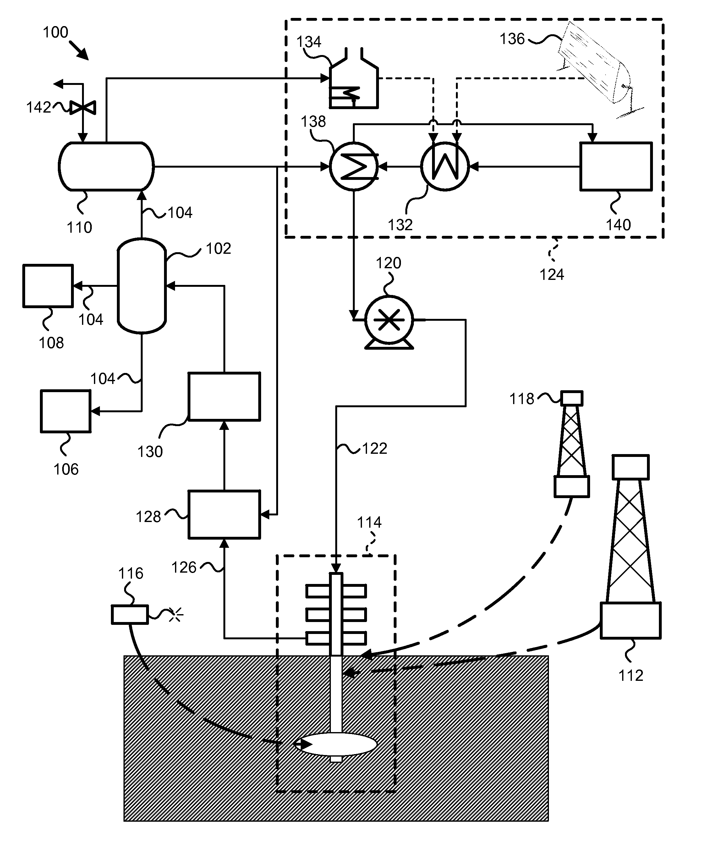
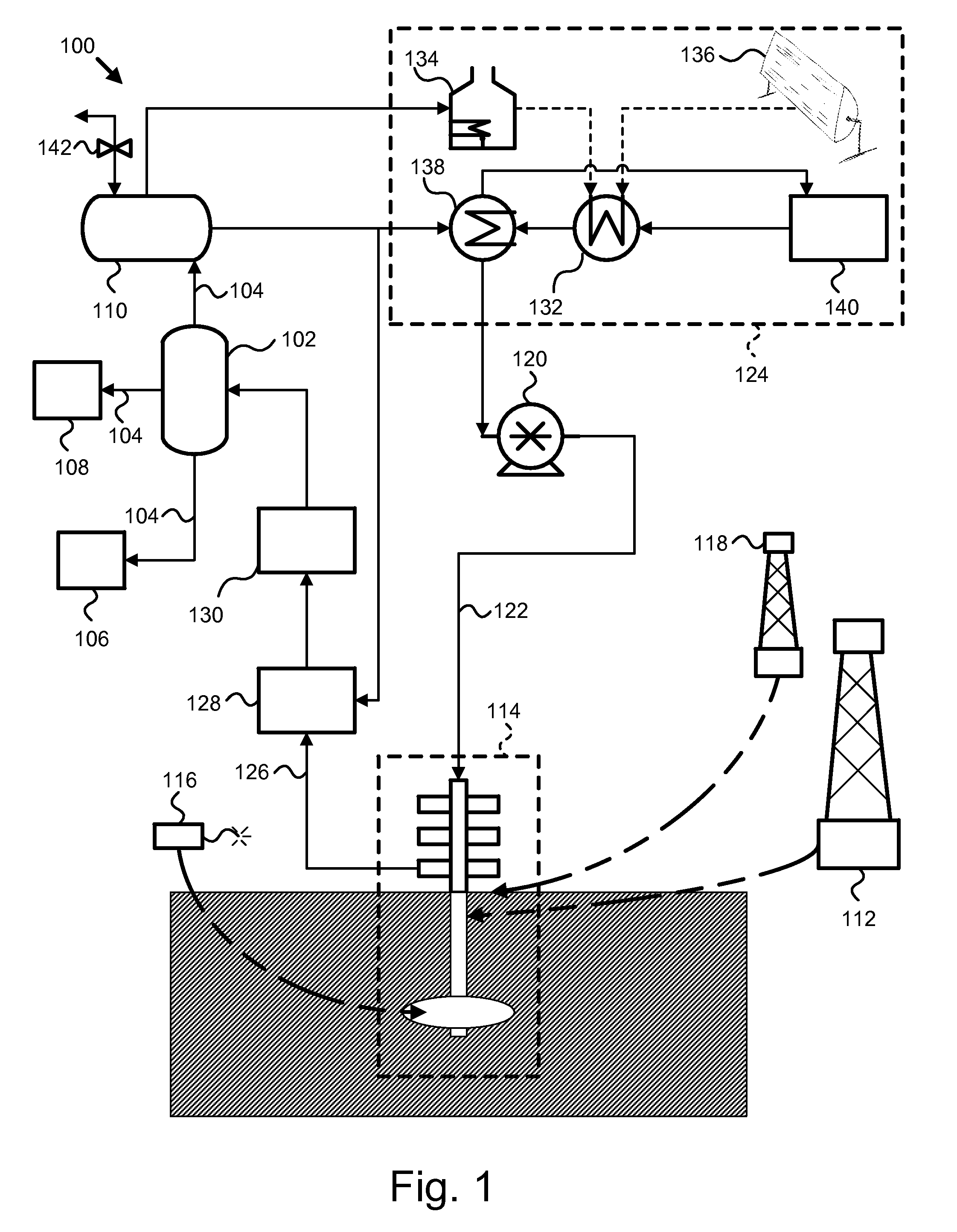
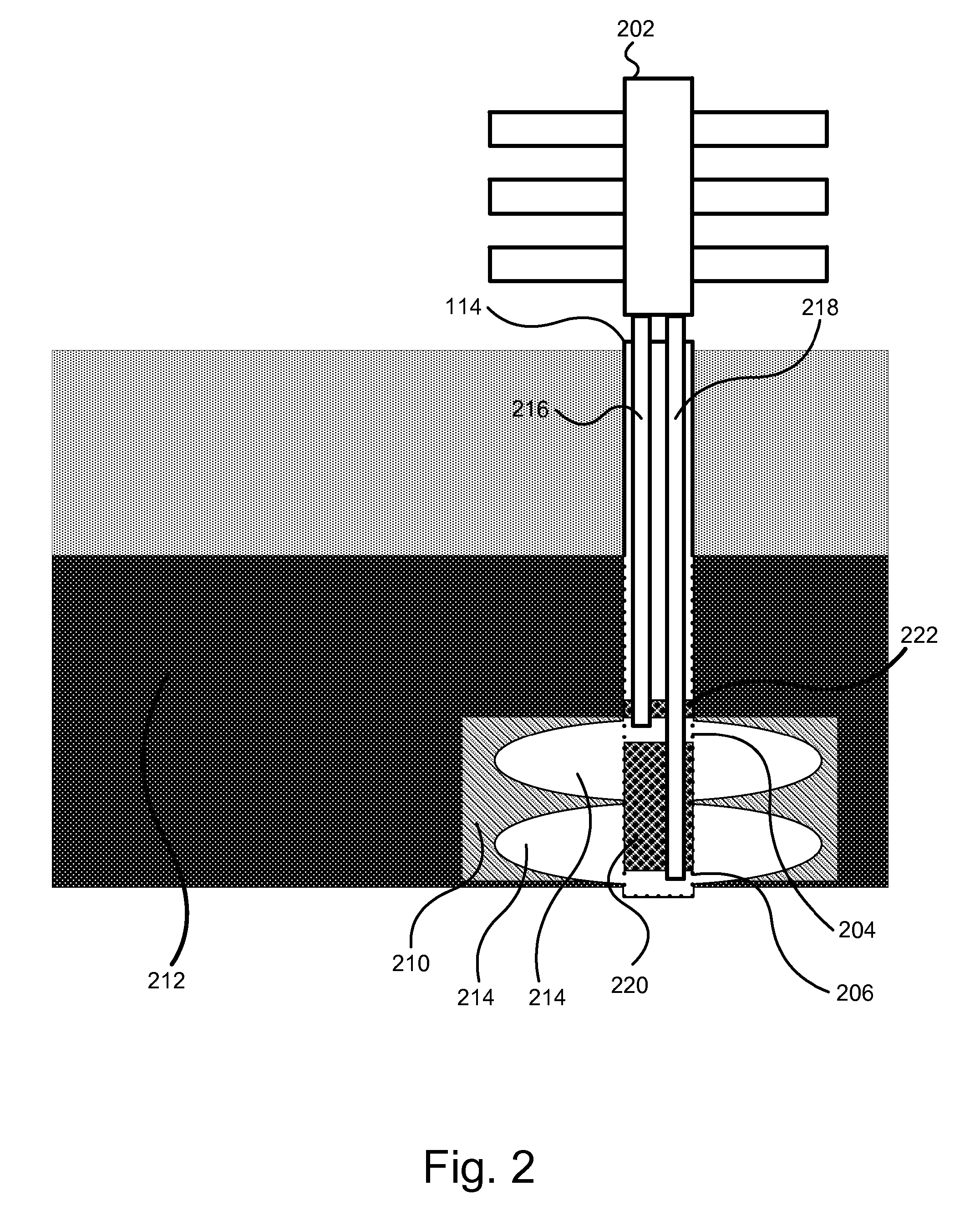
[0044] It will be readily understood that the components of the present invention, as generally described and illustrated in the figures herein, may be arranged and designed in a wide variety of different configurations. Thus, the following more detailed description of the embodiments of the apparatus, system, and method of the present invention, as presented in FIGS. 1 through 15B, is not intended to limit the scope of the invention, as claimed, but is merely representative of selected embodiments of the invention.

[0045] Reference throughout this specification to “one embodiment” or “an embodiment” means that a particular feature, structure, or characteristic described in connection with the embodiment is included in at least one embodiment of the present invention. Thus, appearances of the phrases “in one embodiment” or “in an embodiment” in various places throughout this specification are not necessarily all referring to the same embodiment.

[0046] Furthermore, the described fea...


PUM


Abstract

An apparatus, system, and method are disclosed for in-situ extraction of oil from oil shale. The method comprises drilling a fluid conduit in fluid communication with a top and a bottom of a target zone within an oil shale formation. The method includes stimulating the target zone. The method further includes injecting a heated fluid into the bottom of the target zone such that the heated fluid entrains the kerogen within the target zone into the injected fluid to generate a production fluid. The method concludes with producing the production fluid, containing the in-situ kerogen, from the top of the target zone to the surface.

Description

CROSS-REFERENCES TO RELATED APPLICATIONS [0001] This application claims the benefit of U.S. Provisional Patent Application No. 60 / 716,647 entitled “Apparatus, system, and method for extracting kerogen from shale with a recirculating fluid” and filed on Sep. 14, 2005 for Kevin Shurtleff, which is incorporated herein by reference. This application also claims the benefit of U.S. Provisional Patent Application No. 60 / 820,256 entitled “Apparatus, system, and method for in-situ extraction of oil from oil shale” and filed on Jul. 25, 2006 for Kevin Shurtleff, which is incorporated herein by reference.BACKGROUND OF THE INVENTION [0002] 1. Field of the Invention [0003] This invention relates to the production of oil from oil shale, and more particularly relates to stripping in-situ kerogen from an oil shale formation. [0004] 2. Description of the Related Art [0005] One of the last great untapped fossil fuel resources is oil from oil shale. Traditional oil production methods do not pull oil ...

Claims


Application Information

Patent Timeline
Patent Type & Authority Applications(United States)
IPC IPC(8): E21B43/30E21B43/24
CPCE21B43/305E21B43/24
Inventor SHURTLEFF, JAMES KEVIN
Owner MOUNTAIN WEST ENERGY
Why Eureka
Try Eureka