Measurement while drilling apparatus and method of using the same

a technology of measuring apparatus and drilling shaft, which is applied in the direction of surveying, borehole/well accessories, constructions, etc., can solve the problems of affecting affecting the accuracy of drilling, so as to reduce erosion and wear, prolong the life of the battery, and save the power of the battery

a technology of measuring apparatus and drilling shaft, which is applied in the direction of surveying, borehole/well accessories, constructions, etc., can solve the problems of affecting affecting the accuracy of drilling, so as to reduce erosion and wear, prolong the life of the battery, and save the power of the battery

US20070056771A1Active Publication Date: 2007-03-15PNC BANK NAT ASSOC +2

Image

  • Measurement while drilling apparatus and method of using the same
  • Measurement while drilling apparatus and method of using the same
  • Measurement while drilling apparatus and method of using the same

Examples


Embodiment Construction

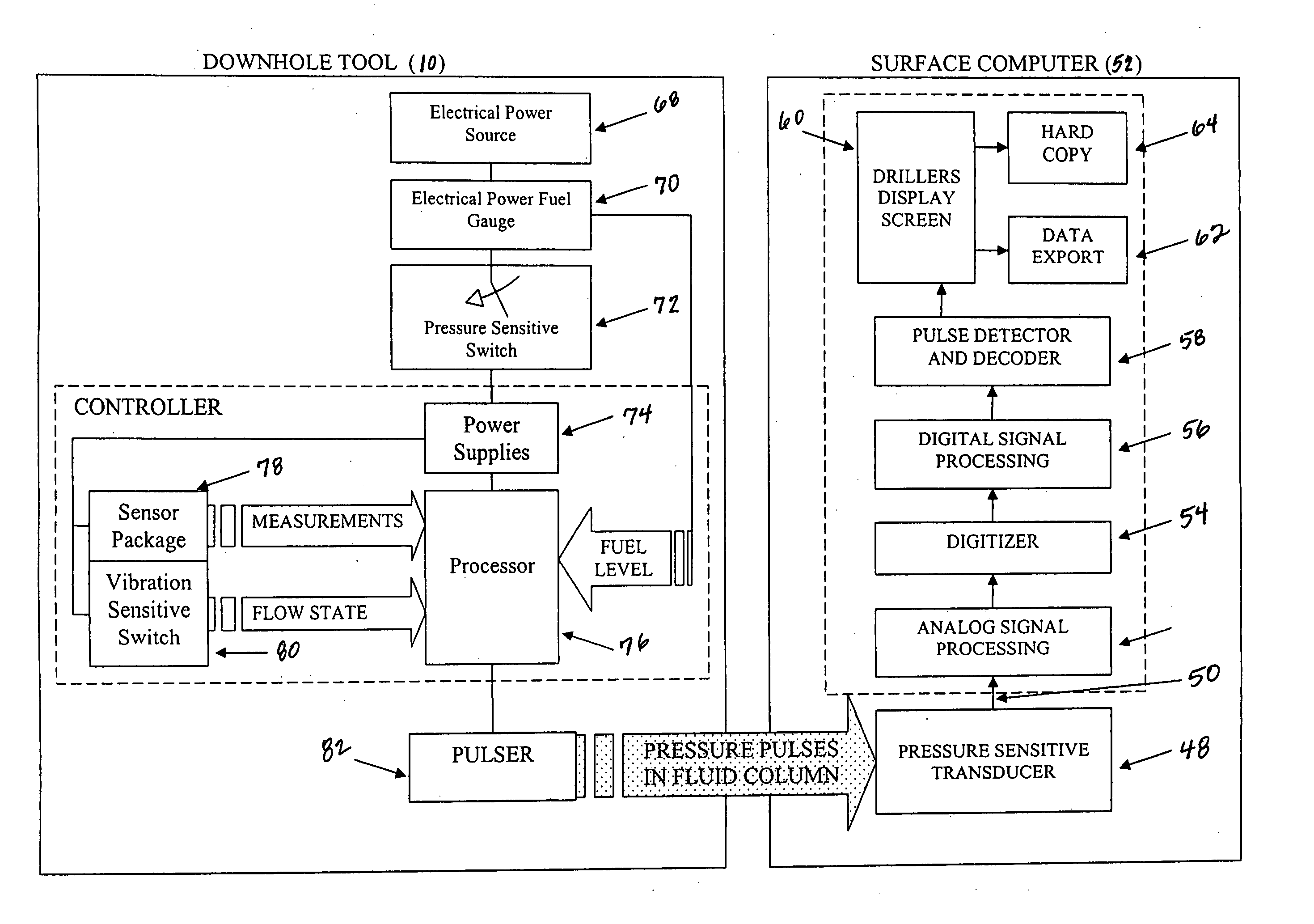
[0100] In a preferred embodiment of the invention, as described in detail below, information of use to the driller is measured at the bottom of a bore hole relatively close to the drilling bit and this information is transmitted to the surface using pressure pulses in the fluid circulation loop. The command to initiate the transmission of data is sent by stopping fluid circulation and allowing the drill string to remain still for a minimum period of time. Upon detection of this command, the downhole tool measures at least one downhole condition, usually an analog signal, and this signal is processed by the downhole tool and readied for transmission to the surface. When the fluid circulation is restarted, the downhole tool waits a predetermined amount of time to allow the fluid flow to stabilize and then begins transmission of the information by repeatedly closing and then opening the pulser valve to generate pressure pulses in the fluid circulation loop. The sequence of pulses sent ...


PUM


Abstract

A method and apparatus used to transmit information to the surface from a subsurface location during the process of drilling a bore hole is described. A novel pressure pulse generator or “pulser” is coupled to a sensor package, a controller and a battery power source all of which reside inside a short section of drill pipe close to the bit at the bottom of the bore hole being drilled. The assembled apparatus or “MWD Tool” can be commanded from the surface to make a measurement of desired parameters and transmit this information to the surface by encoding data in pressure pulses generated by a pulser valve that includes a stator and a rotor which may be open and closed to create pressure pulses.

Description

CROSS-REFERENCE TO RELATED APPLICATIONS [0001] Priority is claimed from provisional patent application U.S. Ser. No. 60 / 716,268, filed on Sep. 12, 2005, and incorporated by referenced herein.FIELD OF INVENTION [0002] In general, the present invention relates to a device, system and method of measuring angle and azimuth in subterranean drilling operations. More particularly, the present invention provides real time feedback during a drilling operation, referred to as “measurement while drilling”, as to the angle and azimuth of the well bore during drilling operation typically associated with wells to indicate drift and direction from the desired drilling parameters by transmission of information from the bottom of a bore hole to the surface by encoding information in pressure pulses in the drilling mud. BACKGROUND OF INVENTION [0003] In the drilling of deep bore holes for the exploration and extraction of crude oil and natural gas, the “rotary” drilling technique has become a commonl...

Claims


Application Information

Patent Timeline
15 Mar 2007
Publication
US20070056771A1
IPC
E21B47/00
CPC
E21B47/187; E21B47/24; E21B47/00; E21B47/12
Inventors
GOPALAN, MANOJ; POE, STEPHEN B.