Printer with sheet sending mechanism

a printing machine and sending mechanism technology, applied in the field of printing machines, can solve the problems of complicated control procedure, predetermined time adjustment in accordance with sheet size, etc., and achieve the effect of simple control procedur

Inactive Publication Date: 2007-03-15
BROTHER KOGYO KK
View PDF21 Cites 51 Cited by
  • Summary
  • Abstract
  • Description
  • Claims
  • Application Information

AI Technical Summary

Benefits of technology

[0013] One object of the present invention is to provide a technique in which a same controlling procedure may be adopted even if the sheet size varies.
[0014] One another object of the invention is to provide a technique in which the appropriate space is formed between the preceding sheet and subsequent sheet even if the sheet size is unknown to the printer.
[0023] Since sheet sending operations of the preceding sheet and the subsequent sheet can be performed continuously, the printing operation can be executed at high speed.
[0027] In the printer of the present invention, when the back edge of the leading or preceding sheet deviates from the supply roller and the leading sheet starts to be sent only by the pair of feed-in rollers, the subsequent sheet starts to be sent by the supply roller. Accordingly, the control procedure becomes extremely simple.
[0028] It is preferred that the feed-in drive roller and the supply roller are rotated by a common motor. It is also preferred that a first condition that the supply roller and the feed-in drive roller rotate in a same direction and a second condition that the supply roller and the feed-in drive roller rotate in an opposite direction can be selected by a selector. Accordingly, the sheet sending mechanism becomes simple.

Problems solved by technology

In the technology disclosed in Japanese Patent Application Laid-Open Publication No. 2001-301998, there is a problem that the predetermined time must be adjusted in accordance with the sheet size.
This makes the control procedure complicated.

Method used


Image

  • Printer with sheet sending mechanism
  • Printer with sheet sending mechanism
  • Printer with sheet sending mechanism

Examples


first embodiment

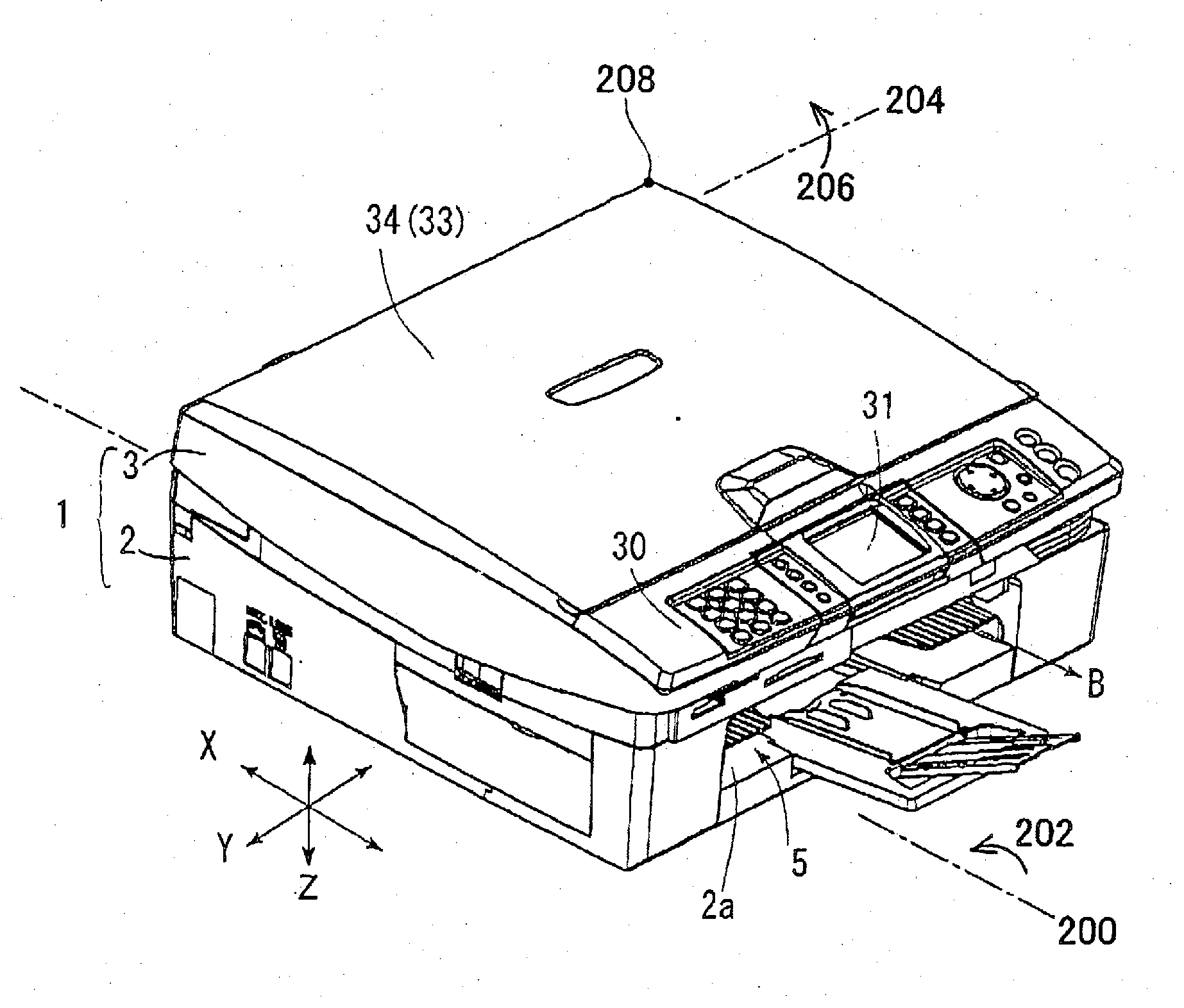
[0078] The first embodiment which crystallizes the present invention is described in detail with reference to the drawings. FIG. 1 shows a perspective view showing an exterior of a multifunction device 1 which comprises a facsimile function, print function, copy function, and scanner function. The multifunction device 1 comprises a sheet sending mechanism for sending a sheet and a printing mechanism for printing characters, graphics, photographic images or the like (generically referred to as “graphic pattern” hereinafter) on the sheet which is sent by the sheet sending mechanism, and provides the sheet printed with the graphic pattern to a user.

[0079] The multifunction device 1 has a lower section case 2 and an upper section case 3. The lower section case 2 is substantially in the form of a box in which an upper surface thereof is opened. The upper section case 3 is connected to a left side face of the lower section case 2 via a hinge (not shown), and can be rotated from the posit...

second embodiment

[0178] Hereinafter, only the differences between the first embodiment and the second embodiment are described and the overlapping explanations are omitted.

[0179] The multifunction device 1 in the second embodiment comprises, as shown in FIG. 23, the lower section case 2 in which a first lower section case 2a and a second lower section case 2b are stacked. An opening section 2c is formed on a front side of the first lower section case 2a and, as shown in FIG. 24, a first paper cassette 5A is inserted therein such that it can be drawn. As shown in FIG. 23, an opening section 2d is formed on a front side of the second lower section case 2b and, as shown in FIG. 24, a second paper cassette 5B is inserted therein such that it can be drawn.

[0180]FIG. 23 shows a state in which the first paper cassette 5A is removed from the lower section case 2 and the second paper cassette 5B is stored in the lower section case 2.

[0181] The upper section case 3 is disposed on an upper side of the lower...


PUM


Abstract

A supply roller for sending a piece of sheet from pieces of sheets stacked within a cassette towards a sheet guide and a pair of feed-in rollers for sending the piece of sheet supplied from the sheet guide towards a printing region are provided within a printer. The pair of feed-in rollers has a feed-in drive roller driven by a motor and a feed-in driven roller driven by the feed-in drive roller. A sending speed of the pair of feed-in rollers is faster than a sending speed of the supply roller, and a sending force of the pair of feed-in rollers is stronger than a sending force of the supply roller. A controller of the printer controls the rotation of the supply roller and the pair of feed-in rollers according to a procedure that does not rely on a position of the sheet sent by the supply roller and the pair of feed-in rollers during the continuous feeding mode.

Description

CROSS REFERENCE TO RELATED APPLICATIONS [0001] This application claims priority to Japanese Patent Applications No. 2005-252136 filed on Aug. 31, 2005, No. 2005-285287 filed on Sep. 29, 2005, and No. 2005-286155 filed on Sep. 30, 2005, and the contents of them are hereby incorporated by reference into the present application. BACKGROUND OF THE INVENTION [0002] 1. Field of the Invention [0003] The present invention relates to a printer for printing on a sheet. The printer of the present invention is generic name of a device comprising: a sheet sending mechanism which successively sends cut sheets; and a printing mechanism which successively prints characters, graphics, photographic images or the like on the sheets sent by the sheet sending mechanism. Not only a printer with a single function, but also a copying device, a facsimile device, a composite device (or a multifunction device) and the like comprising the sheet sending mechanism and printing mechanism also are the printer desc...

Claims


Application Information

Patent Timeline
Patent Type & Authority Applications(United States)
IPC IPC(8): B65H5/02
CPCB41J11/485B41J13/0018B41J25/001B41J19/202B41J2/01B41J13/009B41J23/14B41J25/34B41J23/02B41J25/006
Inventor ASADA, TETSUOKOGA, YUJIIZUCHI, MASATOSHI
Owner BROTHER KOGYO KK
Why Eureka
Try Eureka