Power supply apparatus

a technology of power supply apparatus and power supply voltage, which is applied in the direction of electric variable regulation, process and machine control, instruments, etc., can solve the problems of power consumption by the load increasing, the transient characteristic of the output voltage vo cannot be improved beyond a certain limit, and the output voltage vo to go out of the permitted variation range, etc., to achieve the effect of improving the transient characteristic and reducing the power consumption

Inactive Publication Date: 2007-03-15
ROHM CO LTD
View PDF9 Cites 11 Cited by
  • Summary
  • Abstract
  • Description
  • Claims
  • Application Information

AI Technical Summary

Benefits of technology

[0009] An object of the present invention is to provide a power supply apparatus that offers an output voltage with an improved transient characteristic against an abrupt variation in the output current and that simultaneously permits reduction of the power consumed when the output current increases.

Problems solved by technology

However, in the power supply apparatus that performs the control described above, when the output current Io varies so abruptly as not to be coped with by the feedback loop of the output voltage Vo, a large variation occurs in the output voltage Vo, causing, in the worst case, the output voltage Vo to go out of the permitted variation range (see FIG. 7B).
This is one problem with the conventional power supply apparatus.
This causes the power consumption by the load to increase as the output current Io increases.
This is another problem with the conventional power supply apparatus.
As long as such a configuration is used, the transient characteristic of the output voltage Vo cannot be improved beyond a certain limit.
That is, in the event of an abrupt variation in the output current Io, there still is a risk, in the worst case, of the output voltage Vo going out of the permitted variation range.
Moreover, as the output current Io increases, the power consumption by the load still tends to increase.

Method used


Image

  • Power supply apparatus
  • Power supply apparatus
  • Power supply apparatus

Examples


Embodiment Construction

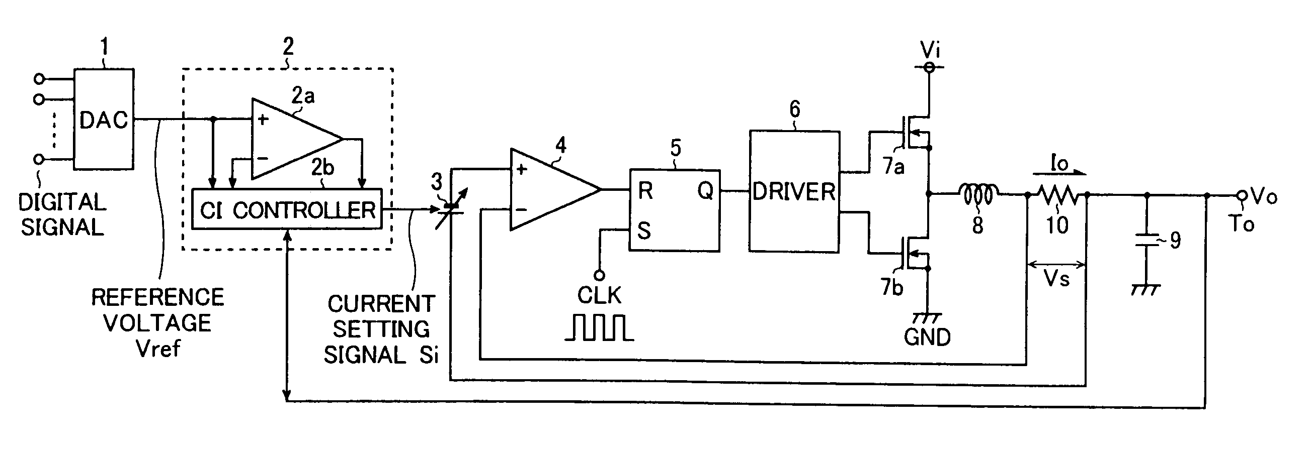
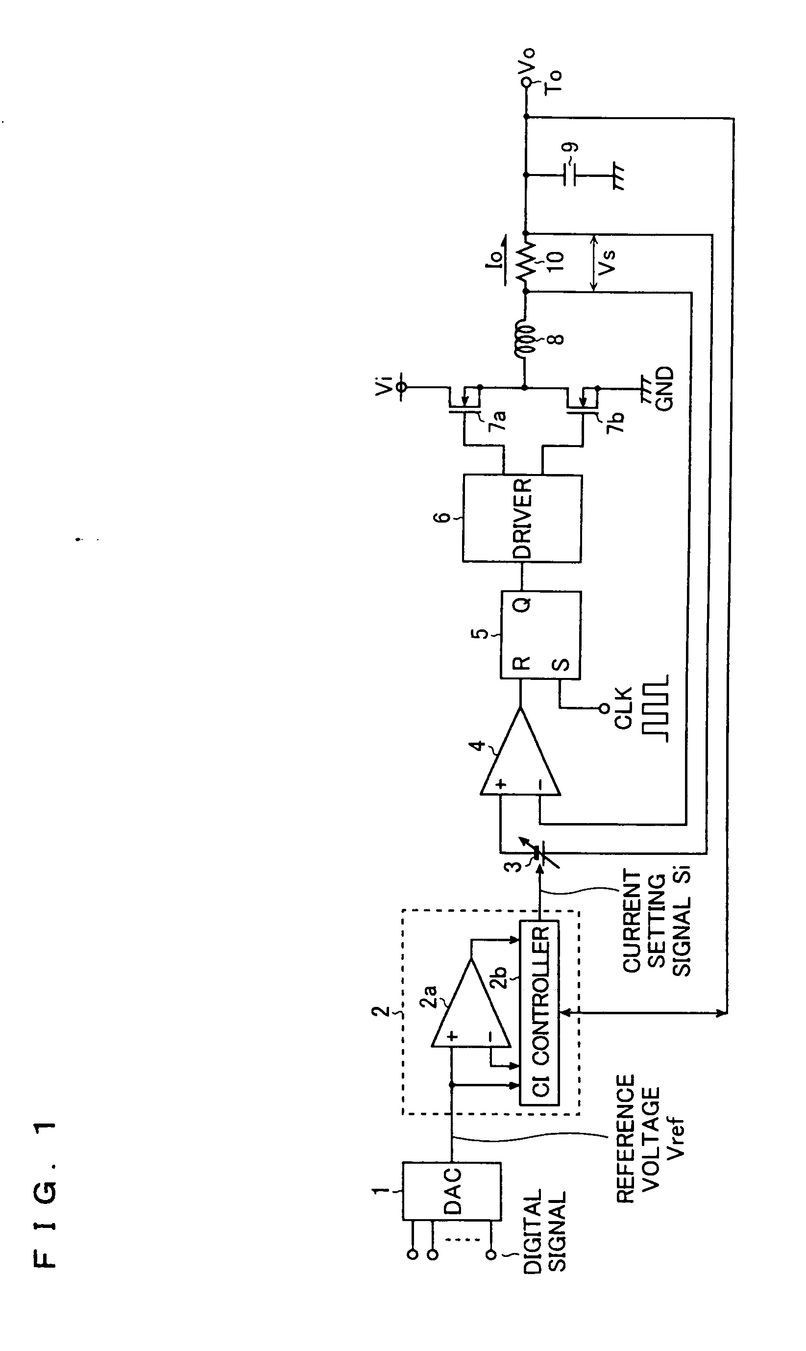
[0019]FIG. 1 is a circuit diagram showing the power supply apparatus of a first embodiment of the invention. As shown in this figure, the power supply apparatus of this embodiment is composed of a digital-to-analog converter 1 (hereinafter referred to as the DAC 1), an output voltage comparison circuit 2, an offset circuit 3, an output current comparator 4, a reset-priority S-R flip-flop 5, an output transistor driving circuit 6 (hereinafter referred to as the driver 6), N-channel MOS field-effect transistors 7a and 7b (hereinafter referred to as the FETs 7a and 7b), an output coil 8, an output capacitor 9, and a sense resistor Io. The power supply apparatus is designed as a DC / DC converter of a synchronous rectification type wherein a desired output voltage Vo obtained from the node between the pair of FETs 7a and 7b connected in series between two different potentials (between an input potential Vi and the ground potential GND) so as to function as switching devices is passed thro...


PUM


Abstract

In a power supply apparatus that is so configured as to produce from an input voltage an output voltage Vo within a predetermined permissible variation range, the output voltage Vo is so controlled as to decrease within the permissible variation range as the output current Io increases. This configuration offers an output voltage with an improved transient characteristic against an abrupt variation in the output current and simultaneously permits reduction of the power consumed when the output current increases

Description

CROSS-REFERENCE TO RELATED APPLICATIONS [0001] This application is a Divisional Application, which claims the benefit of pending U.S. patent application Ser. No. 10 / 822,660, filed April 13, 2004, which claims priority based on Japanese Patent Application No. 2003-111242 filed on Apr. 16, 2003. The disclosure of the prior application is hereby incorporated herein in its entirety by reference.BACKGROUND OF THE INVENTION [0002] 1. Field of the Invention [0003] The present invention relates to a power supply apparatus that generates from an input voltage an output voltage that is permitted to vary within a predetermined permissible variation range. [0004] 2. Description of the Prior Art [0005] Conventionally, in a power supply apparatus that generates from an input voltage Vi an output voltage Vo that is permitted to vary within a predetermined permissible variation range, the output voltage Vo is kept equal to a predetermined reference voltage Vref (a constant level that is not influen...

Claims


Application Information

Patent Timeline
Patent Type & Authority Applications(United States)
IPC IPC(8): G05F1/10G05F1/56H02M3/155H02M3/156H02M3/158H02M3/28
CPCH02M3/156H02M3/1588Y02B70/1466H02M2001/0025H02M2001/0019H02M1/0019H02M1/0025Y02B70/10H02M3/28
Inventor UMEMOTO, KIYOTAKATAKEMURA, KO
Owner ROHM CO LTD
Why Eureka
Try Eureka