
Sensor holder and method for the production thereof

a technology for sensors and holder plates, applied in the field of sensor holders, can solve the problems of high unreliability of sealing processes, insufficient tolerance compliance of components based on mim technology,

Inactive Publication Date: 2007-03-15
ROLF PRETTL
View PDF5 Cites 24 Cited by
  • Summary
  • Abstract
  • Description
  • Claims
  • Application Information

AI Technical Summary

Benefits of technology

[0015] It is thereby possible to offset the sensor component in relation to the plastic carrier. In particular, it is possible to arrange the sensor component in a defined position with respect to a metallic outer carrier, so that dimensional or assembly tolerances can be compensated.
[0088] Depressions of this kind can be produced particularly advantageously in that a basic circuit board is provided with, for example, circular through contactings in a way known per se, and if the basic circuit board is subsequently divided into two individual circuit boards in that a cut is made through the through contactings. The through contactings are thereby “opened”, so that a connection between the terminal pins and the circuit board can thus be made in a simple way.

Problems solved by technology

However, the component based on the MIM technology is not sufficiently tolerance-compliant.
Furthermore, sealing is a highly unreliable process, particularly in the case of the relatively small dimensions of the components which are in question.

Method used


Image

  • Sensor holder and method for the production thereof
  • Sensor holder and method for the production thereof
  • Sensor holder and method for the production thereof

Examples


Embodiment Construction

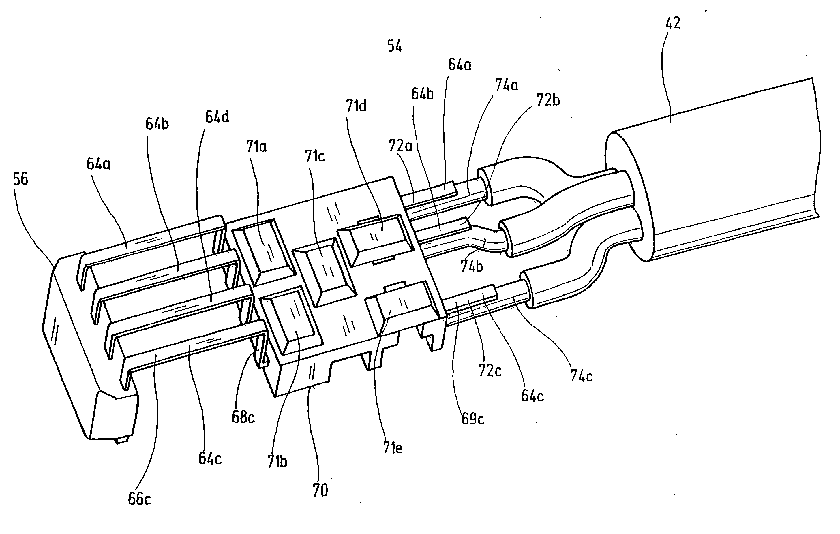
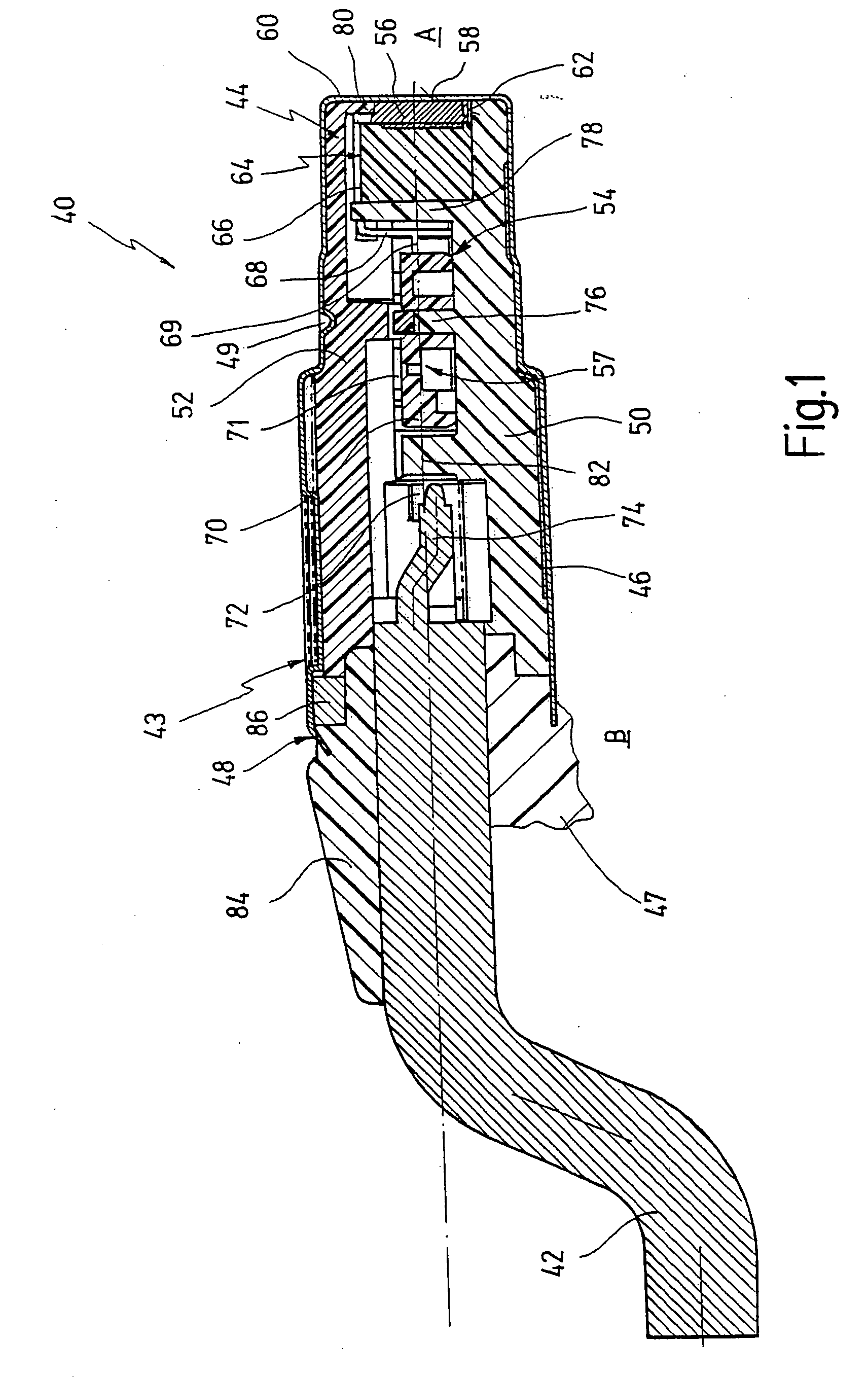
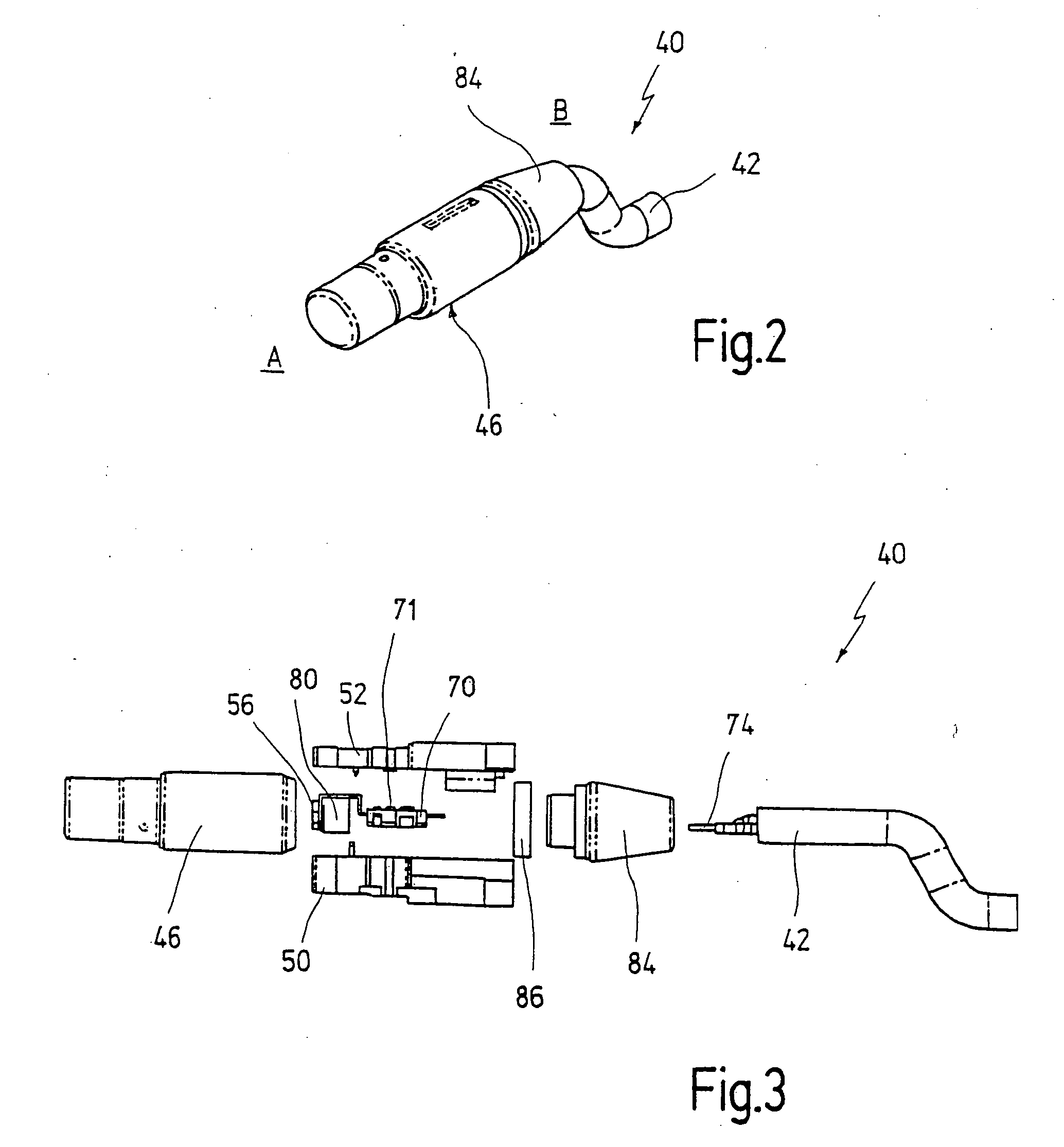
[0098] In FIG. 1-5, a sensor cartridge according to a preferred embodiment of the invention is designated in general by 40.

[0099] The sensor cartridge 40 is connected to an electrical junction cable 42 and contains a holding device 43 for a sensor component.

[0100] The holding device 43 contains a plastic carrier 44 and a metal sleeve 46 surrounding the plastic carrier 44.

[0101] The metal sleeve 46 is closed at a first axial end A. At the second axial end B, the junction cable 42 is led into the metal sleeve 46. The plastic carrier 44 is pushed into the metal sleeve 46 in the direction toward the first axial end A. At the second axial end B, the open end of the metal sleeve 46 is flanged radially inward, this being shown at 48.

[0102] A second radial flanging 49 is provided between the two axial ends A, B and serves for the alternative or additional positive securing of the plastic carrier 44 to the metal sleeve 46.

[0103] The metal sleeve 46 and the plastic carrier 44 are thus pr...


PUM


Abstract

The invention relates to a sensor holder for mounting a sensor component. In one aspect, the sensor holder comprises an elongate holding device, at the first axial end of which the sensor component is mounted and at the second axial end of which a junction cable can be led up, the conductors of which can be connected to terminals of the sensor component. In this case, the holding device has a plastic carrier, on which the sensor component is mounted, and the metallic outer carrier, in particular a metal sleeve, surrounding the plastic carrier.

Description

REFERENCE TO RELATED APPLICATIONS [0001] This application claims priority to and is a continuation of PCT International Application Number PCT / EP2005 / 001868, filed on Feb. 23, 2005, which claims priority under 35 U.S.C. § 119 to German patent application 10 2004 010 321.6 filed on Feb. 24, 2004. The disclosures of the above-described applications are hereby incorporated by reference in their entirety.BACKGROUND OF THE INVENTION [0002] 1. Field of the Invention [0003] The present invention relates to a sensor holder for mounting a sensor component, in particular a Hall sensor, with an elongate holding device, at the first axial end of which the sensor component is mounted and at the second axial end of which a junction cable can be led up, the conductors of which can be connected to terminals of the sensor component. [0004] The present invention relates, furthermore, to a method for the production of a sensor cartridge for a sensor arrangement or for a sensor component. [0005] 2. Des...

Claims


Application Information

Patent Timeline
IPC IPC(8): G01B7/14G01D11/24
CPCG01D11/245
Inventor BORST, PETERBARTH, DIETMAR
Owner ROLF PRETTL
Features
  • Generate Ideas
  • Intellectual Property
  • Life Sciences
  • Materials
  • Tech Scout
  • Unparalleled Data Quality
  • Higher Quality Content
  • 60% Fewer Hallucinations
Learn More