A method and apparatus for correcting gravitational sag in photomasks used in the production of electronic devices

a technology of electronic devices and photomasks, applied in the field of optical lithography devices, can solve the problems of affecting so as to achieve the effect of improving the quality of optical lithography, better devices being produced in the wafer, and reducing the size of optical lithography masks

Inactive Publication Date: 2007-02-01
GOOGLE LLC
View PDF3 Cites 36 Cited by
  • Summary
  • Abstract
  • Description
  • Claims
  • Application Information

AI Technical Summary

Benefits of technology

[0006] The present invention is directed to a mask support arrangement comprised of a pair of separated stages or arms each of which supports a respective novel mask chucking bar. One of said bars is arranged to support and hold a first edge of a thin glass mask and the other of said bars is arranged to, support and hold the second and opposing edge of the mask such that the central portion of the mask spanning the separation between the bars is unsupported. Each bar is particularly designed to apply to the respective edge placed thereon a bending away from the center of the mask that will cause any gravitational induced sag in the unsupported center of the mask to be substantially reduced or eliminated. In this way the unsupported central portion of the mask is effectively flattened. With this reduction in the central sag of the mask the quality of the images reproduced in the photoresist layer on the surface of the wafer is also improved thus resulting in better devices being produced in the wafer.
[0007] In a first embodiment, a pair of separated stage arms, each of which is provided with a respective unique chucking bar having an upper tapered surface. The taper on the bar on the first stage being in opposition to the taper on the bar on the second stage such that when a mask is spanned there between, each bar will apply a respective bending force on the edge of the mask secured thereto such that any gravitationally induced sag in the portion of the mask between the chucking bars will be substantially reduced or eliminated.
[0008] In a second embodiment, each of the separated stage arms is provided with a chucking bar coupled to a respective drive means so that each bar can be separately rotated to apply, to the edges of the mask supported there between forces sufficient to effectively result in a flattening out of the gravitational sag in the center of the mask.
[0009] In a third embodiment, each chucking bar, used on the support arms, has a hinged and cantilevered upper surface and drive means that, when activated, will cause each hinged, cantilevered surface to apply to the mask, supported there between forces sufficient to effectively result in a flattening out of the gravitational sag in the center of the mask.
[0010] In a fourth embodiment, a sensing means, for determining the amount of sag in the center of the mask surface, is coupled to drive the adjustable chucking bars of either the second or third embodiment so as to selectively apply forces to the mask the mask, supported there between sufficient to effectively result in a flattening out of the gravitational sag in the center of the mask.

Problems solved by technology

As semiconductor devices, became smaller, denser and more complex, the images on the masks became correspondingly smaller, denser, and more complex.
However, the overall size of such masks is relatively large and, at present, such masks typically cover an area of 36 square inches or more.
Thus even though the mask surfaces are now initially flatter and more uniform, the weight of large masks is such that when the mask is placed on separated mask supports, the unsupported center of the mask distorts, i.e. sags, due to gravity.
One such technique attempts to do so by altering the focal point of the projection beam to compensate for the amount of sag in the surface of the mask However, to date, such wafer exposure programs and controls are not only very complex but in most cases only partially correct for the focus errors caused by gravitationally induced sagging.

Method used


Image

  • A method and apparatus for correcting gravitational sag in photomasks used in the production of electronic devices
  • A method and apparatus for correcting gravitational sag in photomasks used in the production of electronic devices
  • A method and apparatus for correcting gravitational sag in photomasks used in the production of electronic devices

Examples


first embodiment

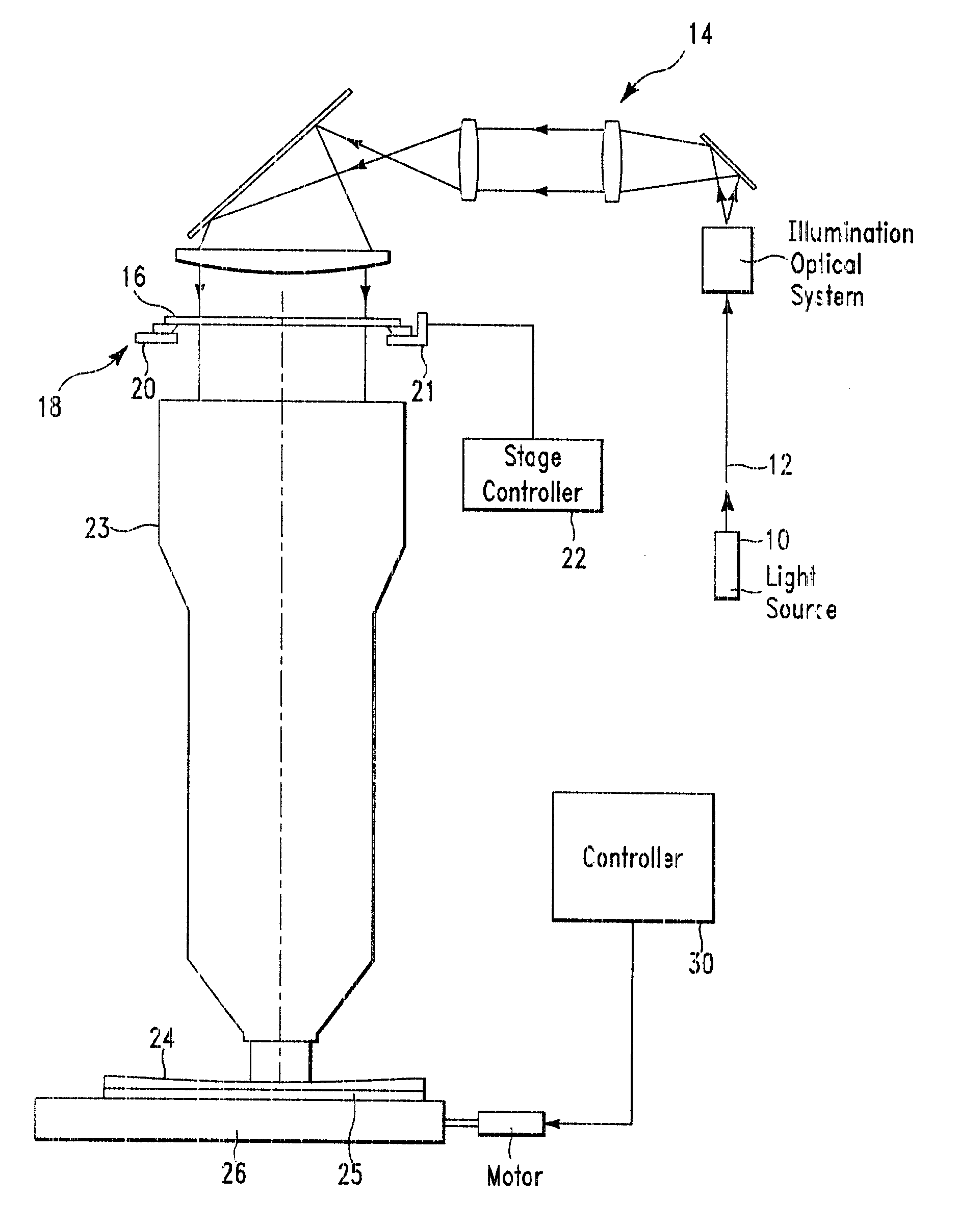
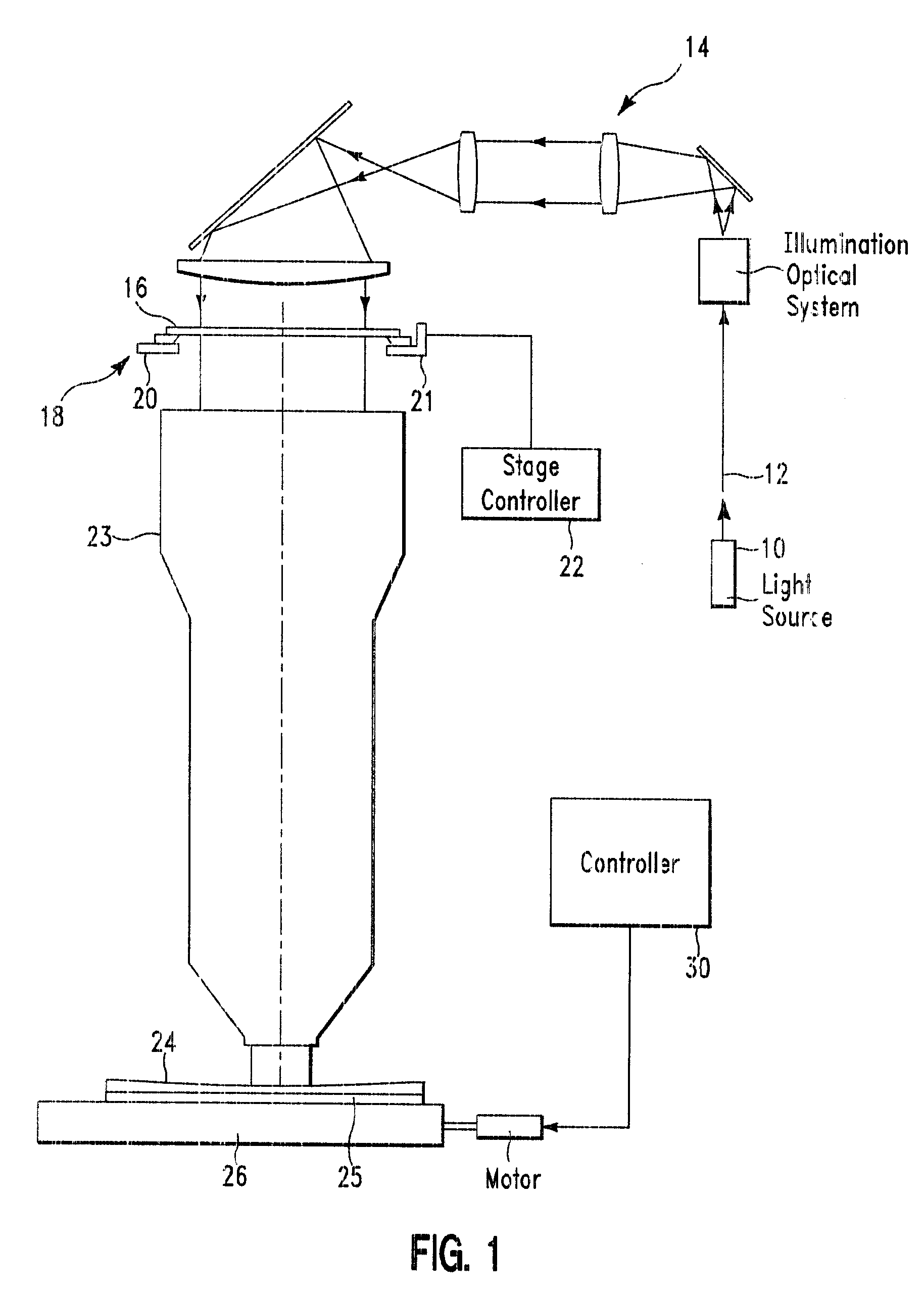
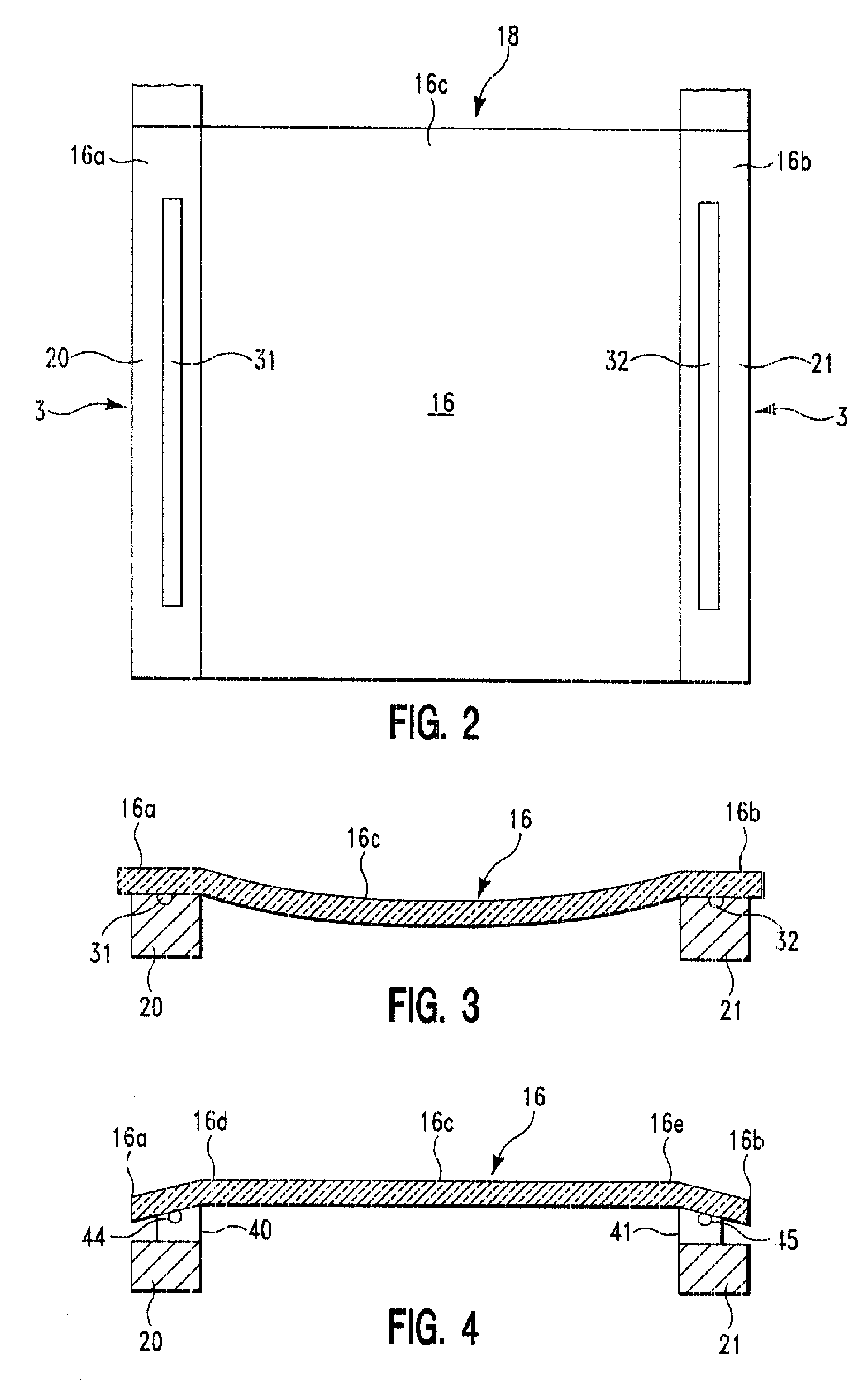
[0030] Turning now to FIG. 4, 5, and 6, the present invention will be described. FIG. 4 is a cross-sectional view of a glass mask 16 having one edge 16a secured to the mask support arm 20 via a respective rigid, parallel, mask holding or chucking bar 40 and its opposite edge 16b secured to the mask support arm 21 via a respective rigid, parallel, mask holding or chucking bar 41. In accordance with the present invention, the chucking bars 40 and 41 are designed such that each will securely hold a respective mask edge 16a, 16b such the center 16c of the mask is supported there between. Each bar 40 and 41 has a top surface designed to securely hold down and apply a bending force on each respective edge 16a and 16b which forces are transmitted to the mask such that any gravitational induced sag in the mask center 16c is reduced, minimized, or substantially eliminated. The present invention achieves this result by providing the chucking bars 40 and 41, supporting the separated edges 16a ...

second embodiment

[0034]FIG. 7 is a perspective view of the present invention wherein each stage arm is adapted to support a rotary chucking bar. In this embodiment each of the stage arms 20, 21, shown in FIG. 6, are identical and each has affixed, at each end, vertical chucking bar supports 51 and 52. Thus, as shown in this FIG. 7 a first vertical support 51 is affixed at a first end 20a of the stage arm 20 and a second vertical support 52 is affixed at the second or opposite end 20b of the arm 20. A chucking bar 53, that can be rotated, is now supported between the vertical supports 51 and 52 by pivot pins 54 and 55 that respectively extend from the vertical supports 51 and 52. These pivot pins 54 and 55 extend into the ends 53a and 53b of the chucking bar 53. The central portion 53c of chucking bar 53 is provided with a vacuum groove 56 that is coupled to a vacuum source 57 via a flexible line 58. Affixed to one of the vertical supports, e.g. vertical support 52 and coupled to the chucking bar 53 ...

third embodiment

[0036] FIGS. 8 is perspective view of the present invention and shows a stage arm 60 that can be substituted for either stage arm 20 or 21 shown in FIG. 2 and FIG. 9 is top planar view of the surface of the stage arm 60. The stage arm 60 is essentially comprised of a main body 61 which has a cantilevered plate 62 fixedly attached to and overlying its upper surface 63. This plate 62 has a free, i.e. cantilevered edge 62a and a fixed edge 62b and further has on its upper surface 64 a vacuum groove 66 that is coupled to a vacuum source 57 via a flexible line 58 by which a mask edge can be secured to the surface of the cantilevered plate 62. The fixed edge 62b of the cantilevered plate 62 is secured to underlying body 61 by a thin, flexible, support rib 67. The body 61 is provided with a plurality of drive devices 68 positioned beneath the plate 62 which can raise or lower the free cantilevered edge 62a as needed to bend or flex a respective mask edge secured thereon as taught above. Th...


PUM


Abstract

In a projection apparatus for projecting optical images, an optical mask support stage having a pair of separated arms. Each arm being provided with a respective mask chucking bar that supports a respective edge of a thin glass mask and applies to the respective edge a bending moment away from the center of the mask to reduce or eliminate any gravitational induced sag in the center of the mask thereby improving the quality of the images projected by the apparatus.

Description

FIELD OF THE INVENTION [0001] The present invention relates generally to optical lithography devices that utilize glass photo-masks bearing patterns or images which can be optically projected to define images in a photoresist layer on the surface of a semiconductor wafer body. These images are then developed and used to produce, in the wafer, a plurality of semiconductor devices, circuits or other such micro-devices more particularly, the present invention is directed to an improved optical lithography device having means therein for reducing or correcting gravitational created distortions, in such glass photo masks. Such correction is achieved by creating a unique mask support or holding assembly that will apply forces to the mask held on the mask support or holding assembly to substantially minimize, offset, or correct, in the mask, any such gravitational created distortion. BACKGROUND OF THE INVENTION [0002] Semiconductor device production lines presently utilize various types of...

Claims


Application Information

Patent Timeline
Patent Type & Authority Applications(United States)
IPC IPC(8): G03B27/42
CPCG03F7/70783G03F7/707
Inventor HIBBS, MICHAEL S.LEVY, MAX G.RACETTE, KENNETH C.
Owner GOOGLE LLC
Why Eureka
Try Eureka