
Evaporated fuel gas adsorbent, evaporated fuel gas trapping apparatus, active carbon and process producing the same

Inactive Publication Date: 2009-02-12
KURARAY CO LTD
View PDF9 Cites 37 Cited by
  • Summary
  • Abstract
  • Description
  • Claims
  • Application Information

AI Technical Summary

Benefits of technology

[0021]It is therefore a first object of the present invention to provide an evaporated fuel gas adsorbent that is capable of reliably preventing both a temperature rise and a temperature fall caused by heat generated in accordance with the adsorption and desorption of evaporated fuel gas and, accordingly, improving the adsorptivity and desorptivity, that is capable of being made more compact, and that is capable of being easily produced. It is a second object of the present invention to provide an evaporated fuel gas trapping apparatus that uses this evaporated fuel gas adsorbent. It is a third object of the present invention to provide an activated carbon that is superior in mechanical strength and in abrasive resistance, that has many pores suitable to adsorb an organic solvent, especially evaporated fuel gas, and that has a high packing density. It is a fourth object of the present invention to provide a process for producing the activated carbon industrially advantageously.
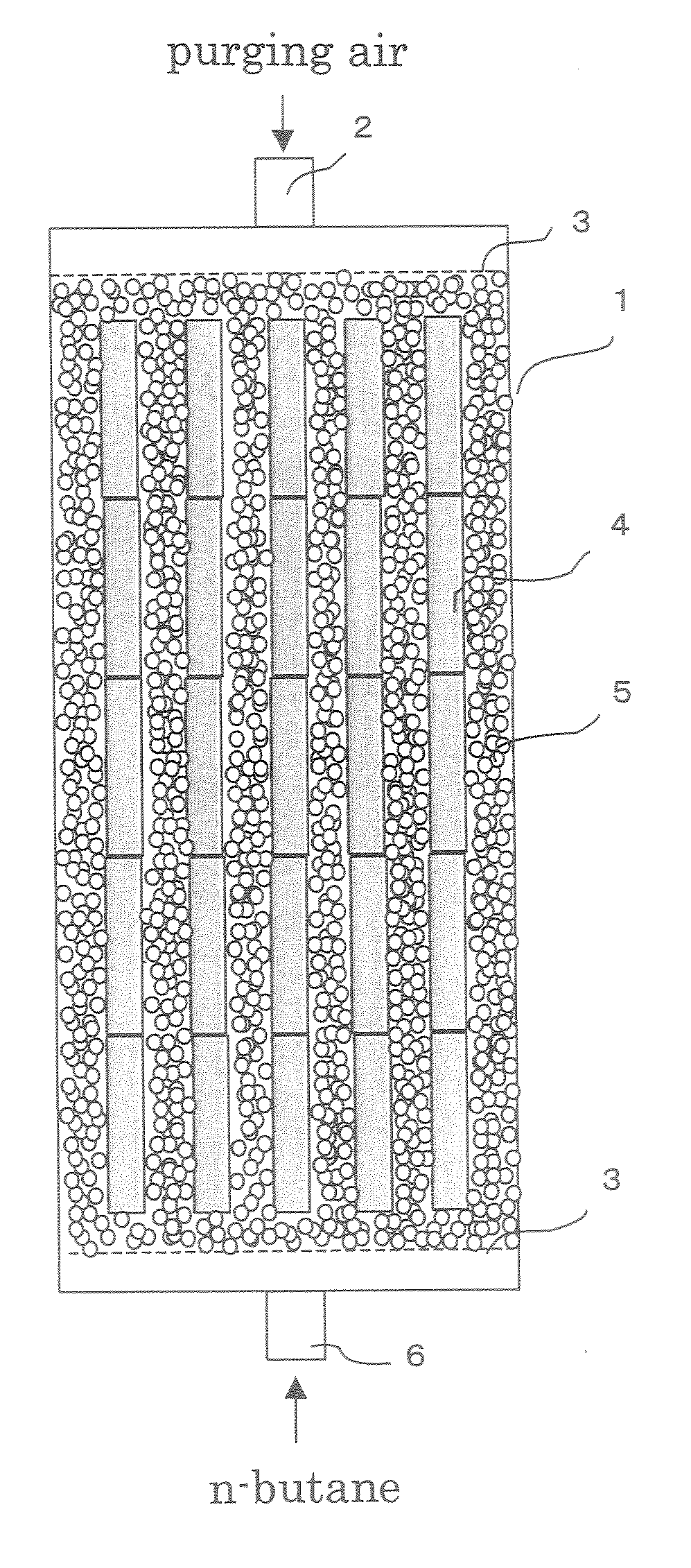
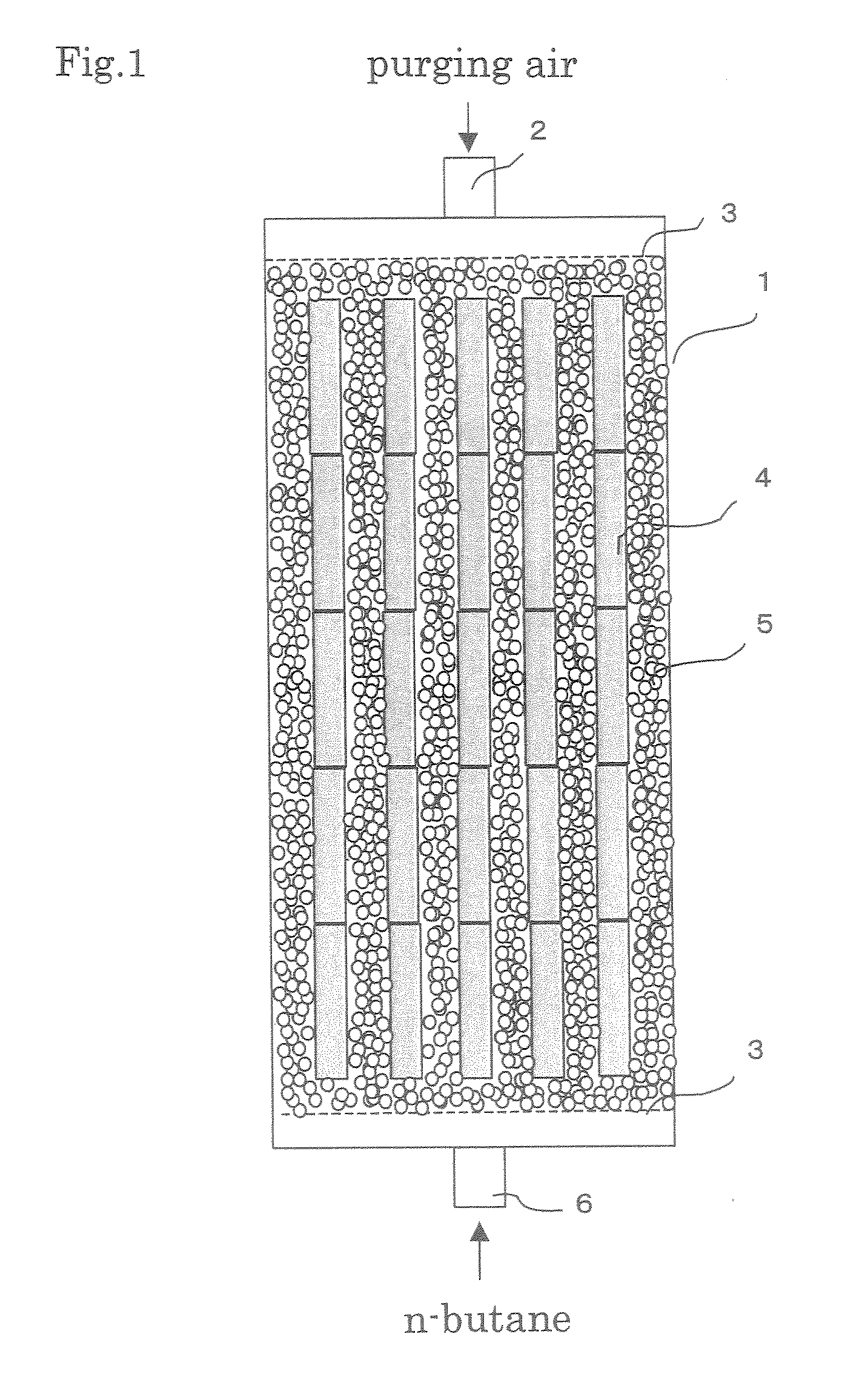
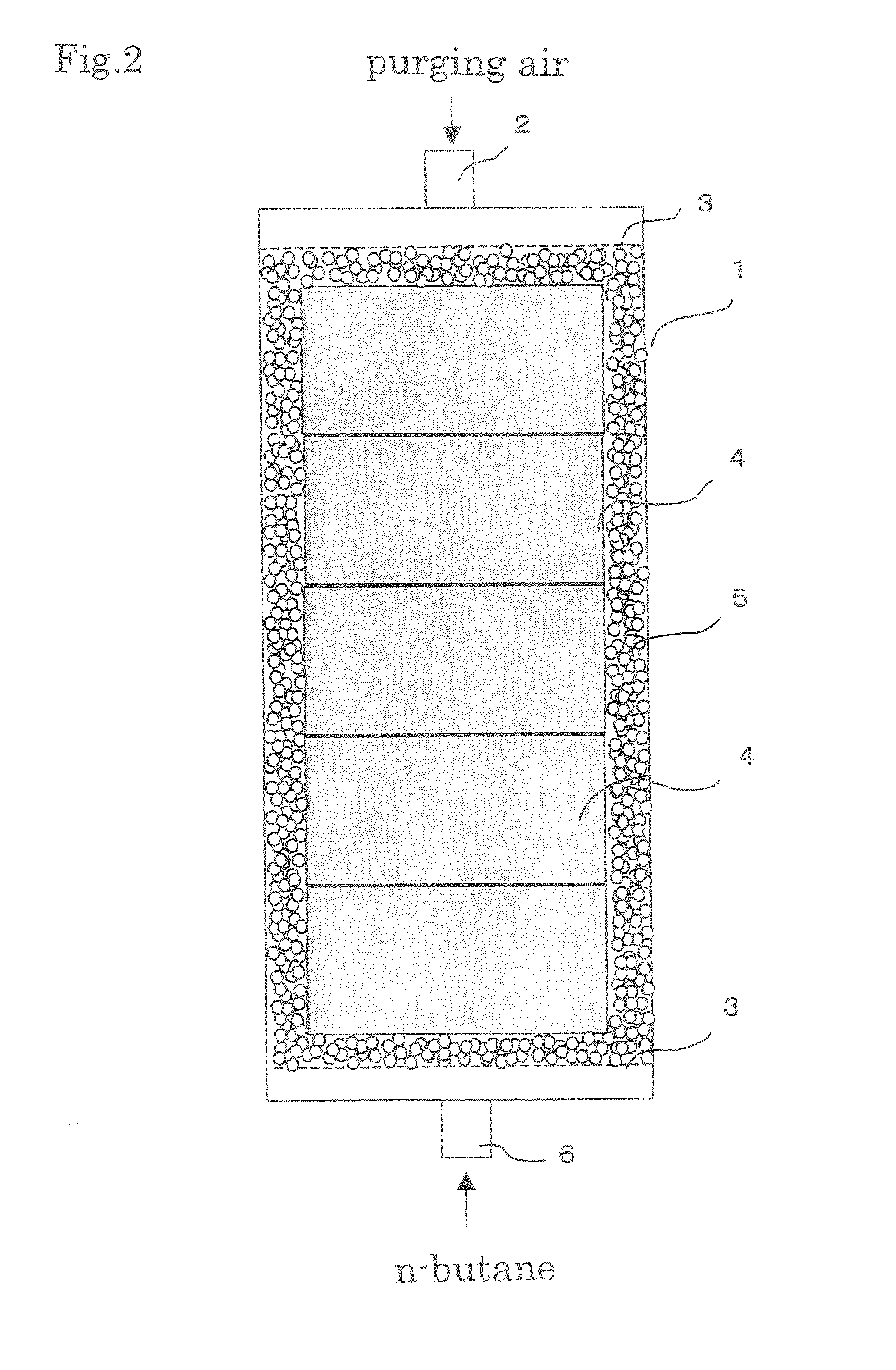
[0022]To achieve the objects, the present inventors have diligently researched from the viewpoint that a temperature change of an adsorptive material caused by the inflow and outflow of adsorption and desorption heat will be prevented if a substance that absorbs or releases heat in response to a phase change (hereinafter, this substance is abbreviated as a “latent-heat storage material”) and activated carbon can be packed into a device at high density in a state of having excellent contact efficiency. As a result unexpectedly, the present inventors have found that the objects can be achieved by employing a simple and low-cost structure in which a latent heat storage medium including flexible-film-made containers in each of which a latent-heat storage material is encased is used together with an adsorptive material, and have reached the present invention. In other words, the present invention is an evaporated fuel gas adsorbent composed of an adsorptive material and a latent heat storage medium including flexible-film-made containers in each of which a latent-heat storage material is encased. Further, the present invention is an evaporated fuel gas trapping apparatus that has this adsorbent.
[0024]According to the evaporated fuel gas adsorbent of the present invention, since a latent-heat storage material is used in a state of being encased in a flexible-film-made container, the whole of the container can be plastically deformed, and the container can be efficiently brought into contact with an adsorptive material participating in the adsorption and desorption of evaporated fuel gas. Therefore, heat caused by the adsorption and desorption thereof can be effectively controlled. Additionally, since the latent-heat storage material can be highly densely packed into the container in solid or liquid form, the limited volume can be effectively utilized, and a device including the latent-heat storage material can be made more compact. Additionally, since the activated carbon of the present invention is superior in the adsorptivity of an organic solvent vapor, especially of evaporated fuel gas, and has both high packing density and high mechanical strength, the activated carbon is suitable for use in a solvent recovery device or in a canister. Additionally, according to the activated-carbon producing process of the present invention, the activated carbon characterized as above can be produced industrially advantageously.

Problems solved by technology

However, the conventional canister has the following essential problems.
However, since the adsorption of evaporated fuel gas to an adsorptive material is based on an exothermic reaction, the temperature of the adsorptive material is increased in accordance with the adsorption of the evaporated fuel gas, so that the adsorptivity exhibits a falling tendency.
Thus, if the adsorptive material is used to adsorb evaporated fuel gas in unchanged form, the adsorptivity and desorptivity of the adsorptive material cannot be fully displayed owing to the above-mentioned conflicting actions during adsorption and desorption.
This is inefficient.
When the conventional techniques are seen from this viewpoint, the activated carbon or the shaped activated carbon described in Patent Documents 1 to 3 mentioned above cannot fully satisfy the requirement.
The thus-produced shaped activated carbon can be improved in mechanical strength and in abrasive resistance, but has difficulty in showing its sufficient performance because the pores are closed with the binder.
The fibrous activated carbon shows a high performance per weight, but does not necessarily have a satisfactory performance per volume.
Additionally, the fibrous activated carbon is expensive, and has difficulty in industrial applicability.
However, since the reaction between carbon and oxygen is an exothermic reaction, the temperature partially runs away, so that a burning reaction is easily caused.
On the other hand, if the temperature is low, the reaction does not easily proceed, and temperature control cannot be easily performed, thus making stable production difficult.
However, in detail, the evaporated-fuel adsorbing agent disclosed thereby is obtained by using the effect of expensive graphite powder, and is hardly adequate from the viewpoint of industrial applicability, for example, because the activation speed is unsatisfactory.
Additionally, although an adsorptive material using a coal is described as favorable, no disclosure is made about what kind of coal is suitable as the coal.
However, if such a medium is flowed from the outside, much time is consumed to control the temperature, which includes that of the inside of the adsorptive material, because the thermal conductivity of the adsorptive material is low although temperature control can be easily performed near the medium.
However, since the evaporated fuel trapping apparatus disclosed by Patent Document 10 uses sensible heat, a thermal disadvantage arises in comparison with a heat quantity needed to improve adsorption and desorption, and a large amount of solid heat storage materials must be mixed therewith to produce a desired effect.
As a result, the ratio of the activated carbon is relatively lowered, and, disadvantageously, a total amount of adsorption is not improved even if the problem of temperature caused during adsorption and desorption is solved.
However, even if the adsorptive material and a liquid in which the microcapsules have been dispersed are equally mixed together and are dried, practical problems will arise.
Additionally, for example, vibrations will cause a separation between the microcapsule encasing the heat storage material and the adsorptive material, thereby making it impossible to fulfill its proper heat-absorbing-and-generating capabilities.
However, the process of compressing the mixture into molded pieces, which is a complex process, is needed, and there is a fear that the microcapsule will be destroyed during the compressing process, and the phase-change substance will leak out therefrom.

Method used


Image

  • Evaporated fuel gas adsorbent, evaporated fuel gas trapping apparatus, active carbon and process producing the same
  • Evaporated fuel gas adsorbent, evaporated fuel gas trapping apparatus, active carbon and process producing the same
  • Evaporated fuel gas adsorbent, evaporated fuel gas trapping apparatus, active carbon and process producing the same

Examples


example 1

[0083]100 parts by weight of anthracite coal powder (0 crucible swelling number, 85% by weight fixed carbon content) whose ash content obtained by water washing was 2.5% by weight was mixed with 10 parts by weight of pitch and 25 parts by weight of coal tar. The resulting mixture was molded into cylindrical pellets each of which is 3 mm in diameter and 3 to 10 mm in length by use of a ring type pelleter produced by Ueda Steel Co., Ltd. These pellets were used as the raw material of activated carbon. The raw material was carbonized by being heated to 750° C. for three hours.

[0084]Thereafter, the carbonized material was heated to 800° C. for five hours under the atmosphere of mixed gas consisting of 10% by volume carbon dioxide and 70% by volume nitrogen containing a 20% by volume water vapor, and continuously underwent the activation process for twenty hours without changes. Thereafter, the material was further heated to 980° C., and continuously underwent the activation process for ...

example 2

[0086]The material that had been molded and carbonized in the same way as in Example 1 was activated at 800° C. for 20 hours under the same mixed gas atmosphere as in Example 1. Thereafter, the material was further heated to 980° C., and continuously underwent the activation process for 18 hours. As a result, granular activated carbon was obtained (Sample 2). Physical properties of Sample 2 are shown in Table 1. The BWC / ASTM of Sample 2 was 15.0.

example 3

[0087]The material that had been molded and carbonized in the same way as in Example 1 was activated at 800° C. for 20 hours under the same mixed gas atmosphere as in Example 1. Thereafter, the material was further heated to 980° C., and continuously underwent the activation process for 12 hours. As a result, granular activated carbon was obtained (Sample 3). Physical properties of Sample 3 are shown in Table 1. The BWC / ASTM of Sample 3 was 13.0.


PUM

PropertyMeasurementUnit
Temperatureaaaaaaaaaa
Pore sizeaaaaaaaaaa

Abstract

The present invention provides an evaporated fuel gas adsorbent, an evaporated fuel gas trapping apparatus that uses the adsorbent, an activated carbon, and a process for producing the activated carbon. The evaporated fuel gas adsorbent is capable of improving adsorptivity and desorptivity by reliably preventing a temperature rise and a temperature fall caused by heat generated in response to the adsorption and desorption of evaporated fuel gas, is capable of achieving a size reduction of the device, and is capable of being easily produced. The activated carbon has high mechanical strength and high abrasive resistance, has many pores suitable to adsorb an organic solvent, especially, evaporated fuel gas, and has a high packing density. The activated-carbon producing process is industrially advantageous. The evaporated fuel gas adsorbent comprises an adsorptive material and latent heat storage mediums including containers each of which is made of a flexible film and in each of which a substance that absorbs or releases heat in response to a phase change is encased. The activated carbon is characterized in that a specific surface area calculated by a BET method (multipoint method) in a nitrogen adsorption isotherm determined from a nitrogen adsorption amount at liquid nitrogen temperature is 1000 to 2500 m2 / g, in that a half-value width of a D-band peak in the neighborhood of 1360 cm−1 in Raman spectroscopic analysis is 120 cm−1 or less, and in that a half-value width of a G-band peak in the neighborhood of 1580 cm−1 in Raman spectroscopic analysis is 100 cm−1 or less.

Description

BACKGROUND OF THE INVENTION[0001]1. Field of the Invention[0002]The present invention relates to an evaporated fuel gas adsorbent an evaporated fuel gas trapping apparatus, activated carbon (also termed “active carbon”), and a process for producing the activated carbon. More particularly, the present invention relates to an evaporated fuel gas adsorbent which comprises latent heat storage mediums including containers each of which is made of a flexible film and in each of which a substance that absorbs or releases heat in response to a phase change, relates to an evaporated fuel gas trapping apparatus using the evaporated fuel gas adsorbent, relates to an activated carbon suitable for the evaporated fuel gas adsorbent, that is 1000 to 2500 m2 / g in the specific surface area calculated by the BET method (multipoint method), that is 120 cm−1 or less in the half-value width of a D-band peak in the vicinity of 1360 cm−1 in Raman spectroscopic analysis, and that is 100 cm−1 or less in the...

Claims


Application Information

Patent Timeline
IPC IPC(8): F02M25/08B01D53/04B01J20/20C01B31/10C01B32/336
CPCB01D53/0407B01D53/0415B01D2253/102B01D2253/306B01D2253/308F02M25/0854B01D2257/704B01D2259/40086B01D2259/4516B01J20/20C01B31/10B01D2253/311C01B32/336
Inventor ABE, SUSUMUISHIMURA, SHIZUOKITAMURA, TAKANORIEGAWA, YOSHIFUMIMIYAKE, AKIRAYAMADA, TAKAYUKIHANAMOTO, TETSUYA
Owner KURARAY CO LTD
Learn More