Thermal module capable of removing dust from heat sink fins by vibration and electronic device thereof

Inactive Publication Date: 2007-03-15
ASUSTEK COMPUTER INC
View PDF6 Cites 42 Cited by
  • Summary
  • Abstract
  • Description
  • Claims
  • Application Information

AI Technical Summary

Problems solved by technology

If the heat generated by the components of the computer cannot be dissipated effectively, the stability and operation speed of the computer will be reduced.
Therefore, if a user does not clean the dust collected on the filter screen 26, the hot air cannot be vented from the vent 18 easily so that the heat generated by the components of the notebook computer 10 cannot be dissipated easily, whi

Method used


Image

  • Thermal module capable of removing dust from heat sink fins by vibration and electronic device thereof
  • Thermal module capable of removing dust from heat sink fins by vibration and electronic device thereof
  • Thermal module capable of removing dust from heat sink fins by vibration and electronic device thereof

Examples


Embodiment Construction

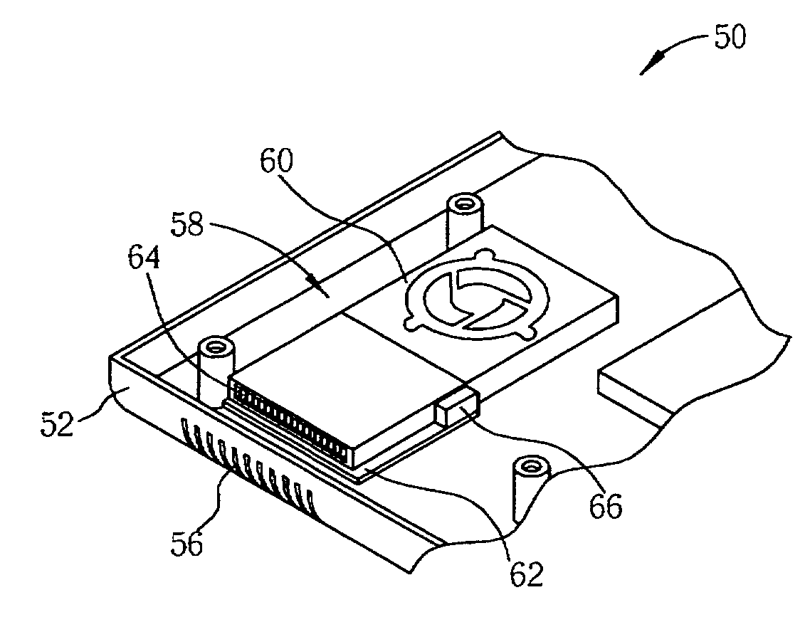
[0015] Please refer to FIG. 3. FIG. 3 is a schematic diagram of an electronic device 50 according to an embodiment of the present invention. The electronic device 50 can be a notebook computer. The electronic device 50 includes a housing 52 for covering internal components. A vent 56 is positioned on a side of the housing 52 for venting hot air. The electronic device 50 further includes a thermal module 58 including a fan 60 installed above an intake (not shown in FIG. 3) and a base 62 installed between the fan 60 and the vent 56 of the housing 52. The base can be a heat sink. A plurality of fins 64 is installed on the base 22 for increasing the heat-dissipating area. The air outside can be sucked in at the intake by the fan 60 of the thermal module 58, be diffused to the plurality of fins 64 on the base 62, and be vented from the vent 56 so as to dissipate the heat generated by the components of the electronic device 50 to outside the housing 52 by heat convection. The electronic d...


PUM


Abstract

A thermal module includes a base, a plurality of fins installed on the base, and a vibrational device installed on the base for vibrating the plurality of fins so as to remove dust from the plurality of fins. An electronic device includes a housing, and a thermal module installed inside the housing. The thermal module includes a base, a plurality of fins installed on the base, and a vibrational device installed on the base for vibrating the plurality of fins so as to remove dust from the plurality of fins.

Description

BACKGROUND OF THE INVENTION [0001] 1. Field of the Invention [0002] The present invention relates to a thermal module, and more particularly, to a thermal module capable of removing dust from heat sink fins by vibration. [0003] 2. Description of the Prior Art [0004] In modern information society, computer systems, such as desktops, notebook computers, servers, and so on, are becoming necessary. The operation speed of a typical computer is becoming faster so that the computer is utilized in a wide variety of fields. Because of the increasing speed, components of the computer generate more heat than before when processing operations. If the heat generated by the components of the computer cannot be dissipated effectively, the stability and operation speed of the computer will be reduced. [0005] Please refer to FIG. 1. FIG. 1 is a diagram of a thermal module 12 of a notebook computer 10 of the prior art. The notebook computer 10 includes a housing 14 for covering internal components. A...

Claims


Application Information

Patent Timeline
IPC IPC(8): H05K7/20
CPCG06F1/203F28G7/00
Inventor YEH, CHING-SUNG
Owner ASUSTEK COMPUTER INC
Why Eureka
Try Eureka