Interaction with wireless sensor devices

a wireless sensor and wireless technology, applied in the field of communication with wireless sensor devices, can solve the problems of difficult interaction with these devices, lack of display or input mechanism for direct interaction, etc., and achieve the effect of convenient discovery, improved interaction capability, and preservation of the ability to interact conveniently

Inactive Publication Date: 2007-03-15
SUN MICROSYSTEMS INC
View PDF7 Cites 156 Cited by
  • Summary
  • Abstract
  • Description
  • Claims
  • Application Information

AI Technical Summary

Benefits of technology

[0007] Accordingly, it would be desirable to provide improved interaction capability with such devices. One aspect of improved interaction capability is to provide a user-friendly mechanism for discovering available wireless sensor devices and for monitoring and configuring them. A small web server can be utilized on the highly constrained sensor devices that supports both HTTP and HTTPS and runs efficiently within the tight computing, networking and memory constraints of mote-like sensor devices. By integrating a secure web server into a sensor device, one can interact with the wireless sensor devices simply and easily using a web browser. Besides the advantage of a familiar user interface and platform independence, this approach also offers well established and familiar communication security in the form of SSL, a protocol supported by virtually every browser. With the addition of an application-level, duty-cycle based approach to low-power listening for incoming service requests to the web server on the highly constrained device, significant improvements can be made power conservation while preserving the ability to interact conveniently, while providing a convenient discovery mechanism.

Problems solved by technology

These devices typically lack a display or input mechanism for direct interaction with users and those users are often unskilled in managing and administering computer systems.
Thus, interaction with these devices can be challenging.

Method used


Image

  • Interaction with wireless sensor devices
  • Interaction with wireless sensor devices
  • Interaction with wireless sensor devices

Examples


Embodiment Construction

)

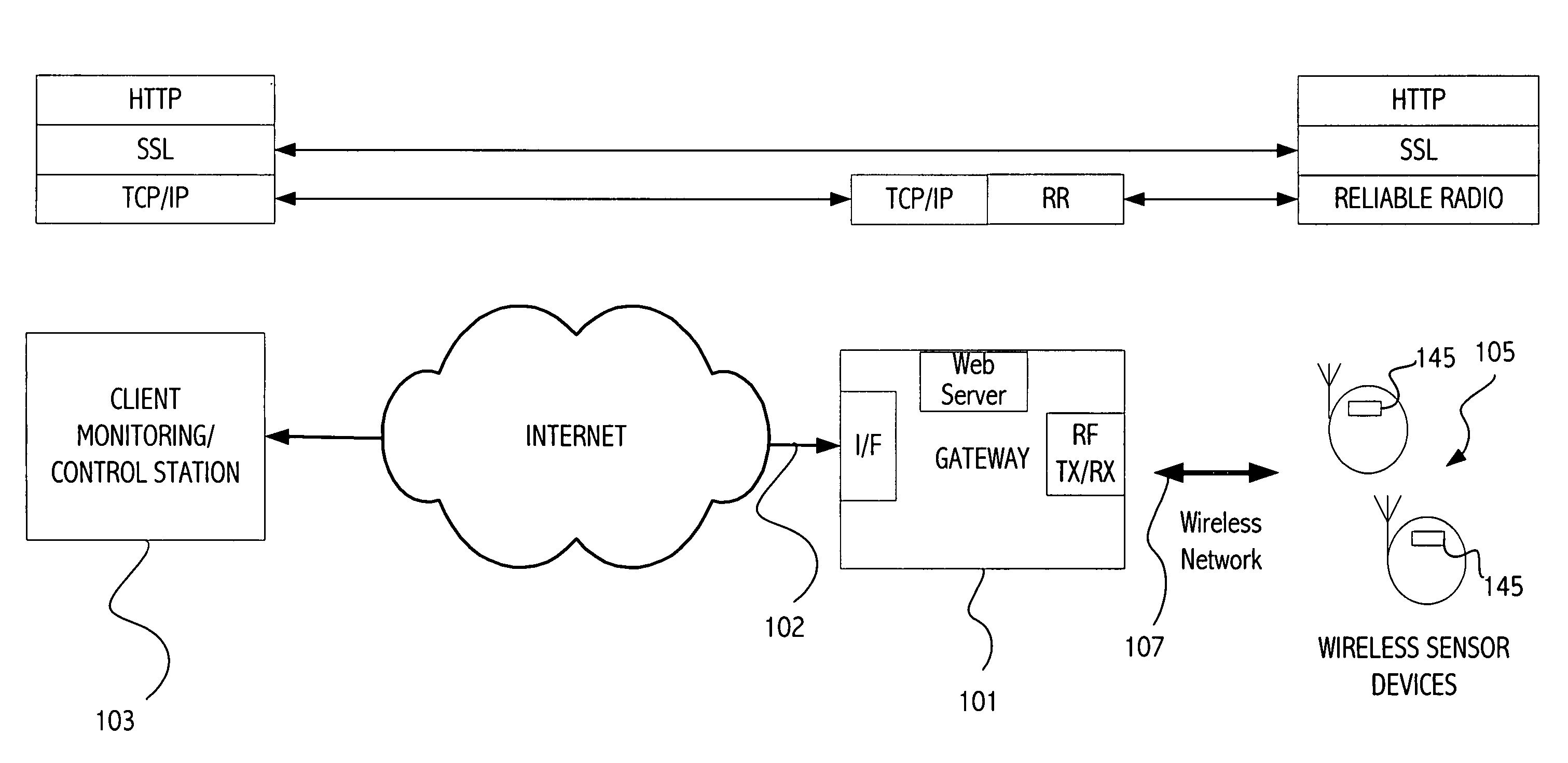
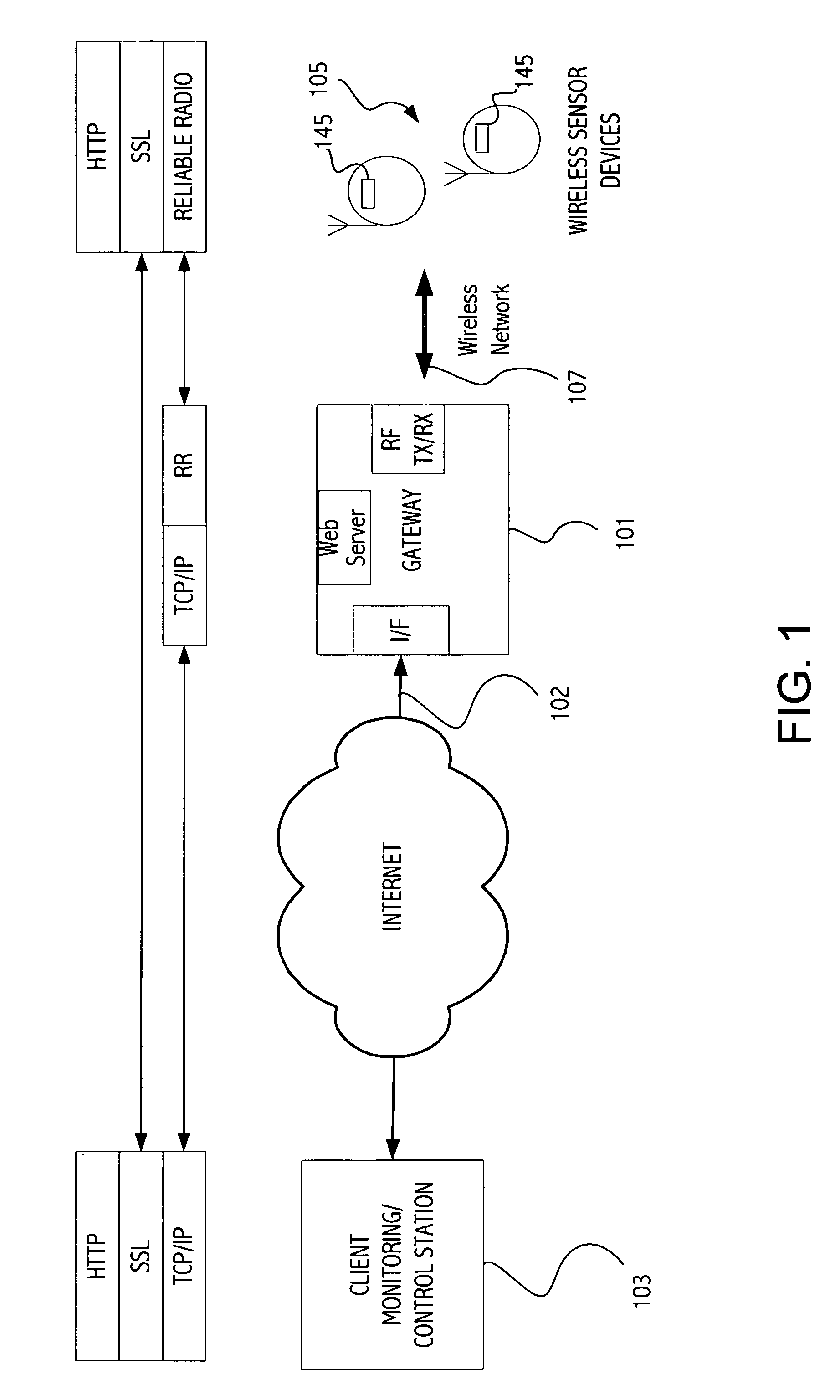
[0016] Referring to FIG. 1, an exemplary gateway-based architecture makes constrained devices such as wireless sensor devices available from the Internet. FIG. 1 illustrates a star topology in which a central device 101 is connected to a client 103 such as a personal computer via a network 102, typically a fast high bandwidth network such as Ethernet or Wifi. The central device 101 acts as a gateway, forming a bridge between the TCP / IP network on one side (or other appropriate protocol) and a wireless sensor network (e.g., IEEE 802.15.4) on the other to communicate with wireless sensor device(s) 105 on the other side of the gateway. While in many embodiments the wireless sensor network is RF, other embodiments may use infrared or other wireless technology. Each wireless sensor device may be mapped to a different TCP-port on the gateway and users can communicate with the with the web server stack running on the wireless sensor device via a standard web browser. An exemplary gateway ...


PUM


Abstract

A client node is communicatively coupled to a gateway node via a TCP / IP network. One or more constrained devices that include a wireless receiver / transmitter circuit communicate with the gateway node via a wireless network. The gateway node includes a web server that provides a dynamic web page accessible by the client node that has a list of the one or more active constrained devices on the wireless network. Each device entry in the list includes a URL that acts as an entry point for the client node to communicate with a web server in a corresponding constrained device. The gateway node automatically discovers a new device on the wireless network and populates the list of the one or more active constrained devices with the newly present constrained device. The new constrained device may be detected based on a periodic message sent by the constrained device indicating the constrained device has turned on its receiver / transmitter circuit for a period of time.

Description

CROSS-REFERENCE TO RELATED APPLICATION(S) [0001] This application claims the benefit of provisional application 60 / 715,438, filed Sep. 9, 2005, entitled “Energy Cost of SSL on Wireless Sensors”, naming Michael Wurm and Vipul Gupta as inventors, which application is incorporated herein by reference in its entirety.BACKGROUND [0002] 1. Field of the Invention [0003] This invention relates to wireless sensor devices and more specifically to communication with wireless sensor devices. [0004] 2. Description of the Related Art [0005] In recent years, a single development—the introduction of network-enabled cell phones was responsible for doubling, between 2001 and 2003, the number of devices connected to the WorldWide Web. As impressive as this trend has been to date, industry watchers predict an even more dramatic increase in the next few years. Today more than 3 billion devices have Web access, and that number is expected to grow to 14 billion within five years, driven primarily by the p...

Claims


Application Information

Patent Timeline
Patent Type & Authority Applications(United States)
IPC IPC(8): H04L12/56
CPCH04L67/12
Inventor GUPTA, VIPULWURM, MICHAEL
Owner SUN MICROSYSTEMS INC
Why Eureka
Try Eureka