Rolling bearing apparatus

Inactive Publication Date: 2007-03-15
JTEKT CORP
View PDF8 Cites 2 Cited by
  • Summary
  • Abstract
  • Description
  • Claims
  • Application Information

AI Technical Summary

Benefits of technology

[0013] In accordance with the rolling bearing apparatus of the invention, since the concave portion for weight saving is formed such that the surface intersecting the direction of the contact angle of the rolling body forms the conical surface,

Problems solved by technology

It becomes extremely hard to intend weight sa

Method used


Image

  • Rolling bearing apparatus
  • Rolling bearing apparatus

Examples


Example

[0016] A description will be given below of an embodiment in accordance with the invention with reference to the accompanying drawings.

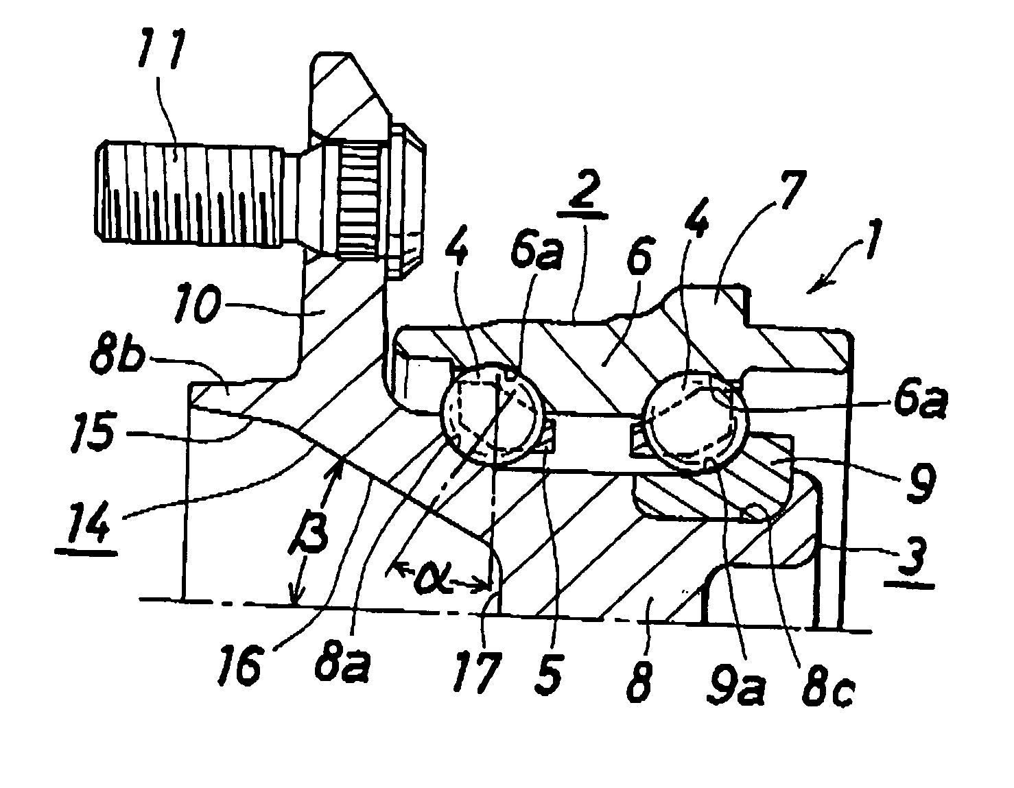
[0017]FIG. 1 shows an embodiment of a rolling bearing apparatus in accordance with the invention. In the following description, right and left mean right and left in FIG. 1. In this case, a left side shows an outer side of a vehicle, and a right side shows an inner side of the vehicle.

[0018] A rolling bearing apparatus 1 is used as a hub unit for a driven wheel of a motor vehicle, and is provided with a fixed side raceway member 2 fixed to a vehicle body side, a rotating side raceway member 3 to which a wheel is attached, balls 4 corresponding to a plurality of rolling elements arranged in two rows between both the members 2 and 3, and a cage 5 holding the balls 4 in each of the rows.

[0019] A type of the bearing is constituted by a double row angular ball bearing, and the balls 4 are arranged between the fixed side raceway member 2 corresponding t...


PUM


Abstract

A rotating side raceway member has a solid portion, and a concave portion for weight saving is provided on an end surface of the solid portion. The concave portion is formed in such a manner that a surface intersecting a direction of a contact angel of a rolling element forms a conical surface having a predetermined angle with respect to an axial direction.

Description

BACKGROUND OF THE INVENTION [0001] The invention relates to a rolling bearing apparatus which is preferably used as a hub unit for a driven wheel of a motor vehicle. [0002] A rolling bearing apparatus 31 used as a hub unit for a driven wheel of a motor vehicle is provided with a fixed side raceway member 32 doubling as an outer ring of a rolling bearing, a rotating side raceway member 33 doubling as an inner ring of the rolling bearing, two rows of balls 34 arranged between both the members 32 and 33 so as to form a predetermined contact angle, and a cage 35 holding each of the rows of balls 34, for example, as shown in FIG. 2. The fixed side raceway member 32 is attached to a vehicle body side suspension apparatus, and a wheel is attached to the rotating side raceway member 33. The rotating side raceway member 33 is constituted by a solid inner shaft 36 having a first inner ring raceway groove 36a, and an inner ring 37 having a second inner ring raceway groove 37a and fitted to the...

Claims


Application Information

Patent Timeline
IPC IPC(8): F16C13/00
CPCB60B27/0005B60B27/0084B60B27/0094F16C33/581Y02T10/86F16C2326/02F16C19/186F16C33/586
Inventor TAKADA, YOSHITOYU, CHANGXINNAGATA, SYUUJIINOUE, SHIGERU
Owner JTEKT CORP
Why Eureka
Try Eureka