Systems and methods for fluorescence detection with a movable detection module

a fluorescence detection and module technology, applied in the field of fluorescence detection systems, can solve the problems of difficult monitoring of the progress of amplification, limited use of optical readers, and various drawbacks of existing fluorometers

Inactive Publication Date: 2007-03-15
BIO RAD LAB INC
View PDF31 Cites 28 Cited by
  • Summary
  • Abstract
  • Description
  • Claims
  • Application Information

AI Technical Summary

Benefits of technology

[0013] According to another aspect of the invention, the detection module may include two or more excitation light generators and two or more emission light detectors arranged to form two or more excitation / detection pairs. In one embodiment, the excitation / detection pairs are arranged such that each excitation / detection pair is simultaneously positionable in optical contact with a different one of the plurality of wells. In an alternative embodiment, excitation / detection pairs are arranged such that when a first one of the excitation / detection pairs is positioned in optical contact with any one of the plurality of wells, a different one of the excitation / detection pairs is not in optical contact with any one of the plurality of wells. In some embodiments, the detection module is detachably mounted on the support structure, thereby enabling a user to replace the detection module with a different detection module.

Problems solved by technology

The usefulness of optical readers is limited by the need to remove the sample plate from the thermal cycler, making it difficult to monitor the progress of amplification.
Existing fluorometers suffer from various drawbacks.
As the number of sample wells in an array increases, this becomes an increasingly time-consuming task, and errors in calibration may introduce significant errors in subsequent measurements.
This limits an experimenter's ability to adapt a fluorometer to a different application.
Many existing fluorometers make it difficult for an experimenter to reconfigure light sources or detectors, thus limiting the variety of fluorescent labels that may be used.
It is also difficult to perform concurrent measurements of a number of different fluorescent labels that may be present in a sample (or in different samples).
Existing fluorometers, however, do not facilitate such multiple-label experiments.
Others provide multiple light sources and detectors to allow detection of multiple labels; however, these configurations often allow only one label to be probed at a time because the excitation wavelength of one label may overlap the emission wavelength of another label; excitation light entering the detector would lead to incorrect results.
Probing multiple labels generally cannot be done in parallel, slowing the data collection process.

Method used


Image

  • Systems and methods for fluorescence detection with a movable detection module
  • Systems and methods for fluorescence detection with a movable detection module
  • Systems and methods for fluorescence detection with a movable detection module

Examples


Embodiment Construction

[0024] An exemplary apparatus embodiment of the present invention will be described with reference to the accompanying drawings, in which like reference numerals indicate corresponding parts. Methods of using the apparatus will also be described. It is to be understood that embodiments shown and described herein are illustrative and not limiting of the invention.

I. Exemplary Apparatus

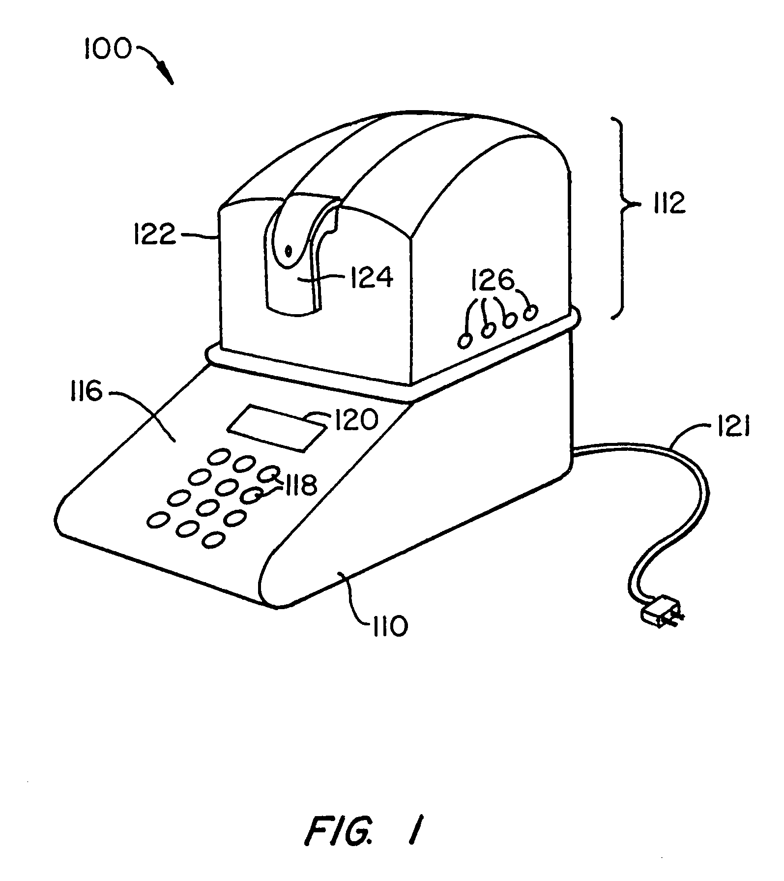
[0025]FIG. 1 is a perspective view of a thermal cycling apparatus 100 according to an embodiment of the present invention. Apparatus 100 consists of a base unit 110 and a lid assembly 112. Base unit 110, which may be of conventional design, provides power and control functions for a thermal cycling process via conventional electronic components (not shown), such as programmable processors, clocks, and the like. Base unit 110 also provides a user interface 116 that may include a keypad 118 and an LCD display screen 120, enabling a user to control and monitor operation of the thermal cycler. Base unit ...


PUM

PropertyMeasurementUnit
melting temperaturesaaaaaaaaaa
fluorescence detectionaaaaaaaaaa

Abstract

A fluorescence detection apparatus for analyzing samples located in a plurality of wells in a thermal cycler and methods of use are provided. In one embodiment, the apparatus includes a support structure attachable to the thermal cycler and a detection module movably mountable on the support structure. The detection module includes one or more channels, each having an excitation light generator and an emission light detector both disposed within the detection module. When the support structure is attached to the thermal cycler and the detection module is mounted on the support structure, the detection module is movable so as to be positioned in optical communication with different ones of the plurality of wells. The detection module is removable from the support structure to allow easy replacement.

Description

CROSS-REFERENCES TO RELATED APPLICATIONS [0001] This application is a continuation of application Ser. No. 10 / 431,708, filed May 8, 2003, entitled “Systems and Methods for Fluorescence Detection with a Movable Detection Module,” which disclosure is incorporated herein by reference for all purposes.BACKGROUND OF THE INVENTION [0002] The present invention relates in general to fluorescence detection systems and in particular to a fluorescence detection system having a movable excitation / detection module for use with a thermal cycler. [0003] Thermal cyclers are known in the art. Such devices are used in a variety of processes for creation and detection of various molecules of interest, e.g., nucleic acid sequences, in research, medical, and industrial fields. Processes that can be performed with conventional thermal cyclers include but are not limited to amplification of nucleic acids using procedures such as the polymerase chain reaction (PCR). Such amplification processes are used to...

Claims


Application Information

Patent Timeline
Patent Type & Authority Applications(United States)
IPC IPC(8): C12Q1/68C12P19/34C12M3/00B01L7/00G01N21/64
CPCB01L7/52B01L2300/0654B01L2300/0829C12Q1/686G01N21/276G01N21/6452B01L2300/1822G01N2201/0446
Inventor KORDUNSKY, IGORGOLDMAN, JEFFREY A.FINNEY, MICHAEL J.
Owner BIO RAD LAB INC
Why Eureka
Try Eureka