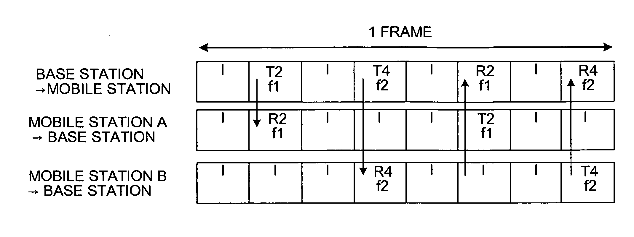
Method of assigning radio channel
a radio channel and radio communication technology, applied in the direction of data switching networks, transmission path division, wireless communication, etc., can solve the problems of increasing the interference between base stations and system not recognizing the received level of interference, and achieve the effect of reducing the probability of receiving
- Summary
- Abstract
- Description
- Claims
- Application Information
AI Technical Summary
Benefits of technology
Problems solved by technology
Method used
Image
Examples
first embodiment
[0016] At first, a channel assignment method according to the present invention is explained below.
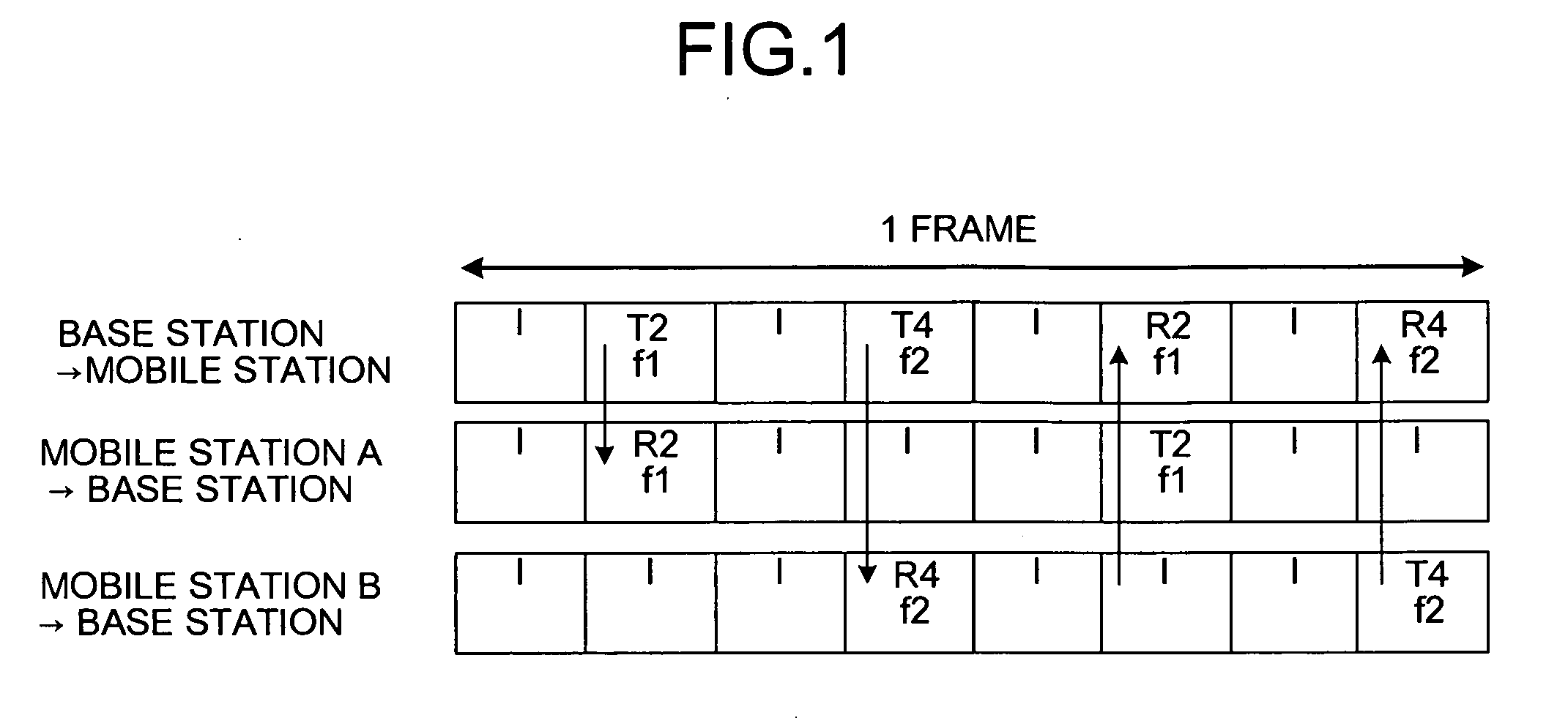
[0017]FIG. 1 is a diagram of a slot arrangement in a radio communication system that employs, for example, four-channel multicarrier TDMA / TDD (Time Division Multiple Access / Time Division Duplex). In the radio channel assignment method according to the first embodiment, as an example, a base station assigns a transmission / reception slot that is divided into four in a time-axis direction, to mobile stations. At this time, a carrier on a frequency axis is assigned to each slot to be assigned, the carrier having an up-link interference level that is measured at a reception timing by a local station and is a value less than a specific threshold value. In other words, FIG. 1 indicates an example in which a mobile station (1) performs communication with a base station using a carrier f1 in a slot #2 (T2→R2), and a mobile station (2) performs communication with a base station using a carrier f...
second embodiment
[0036] A channel assignment method according to the present invention is explained below.
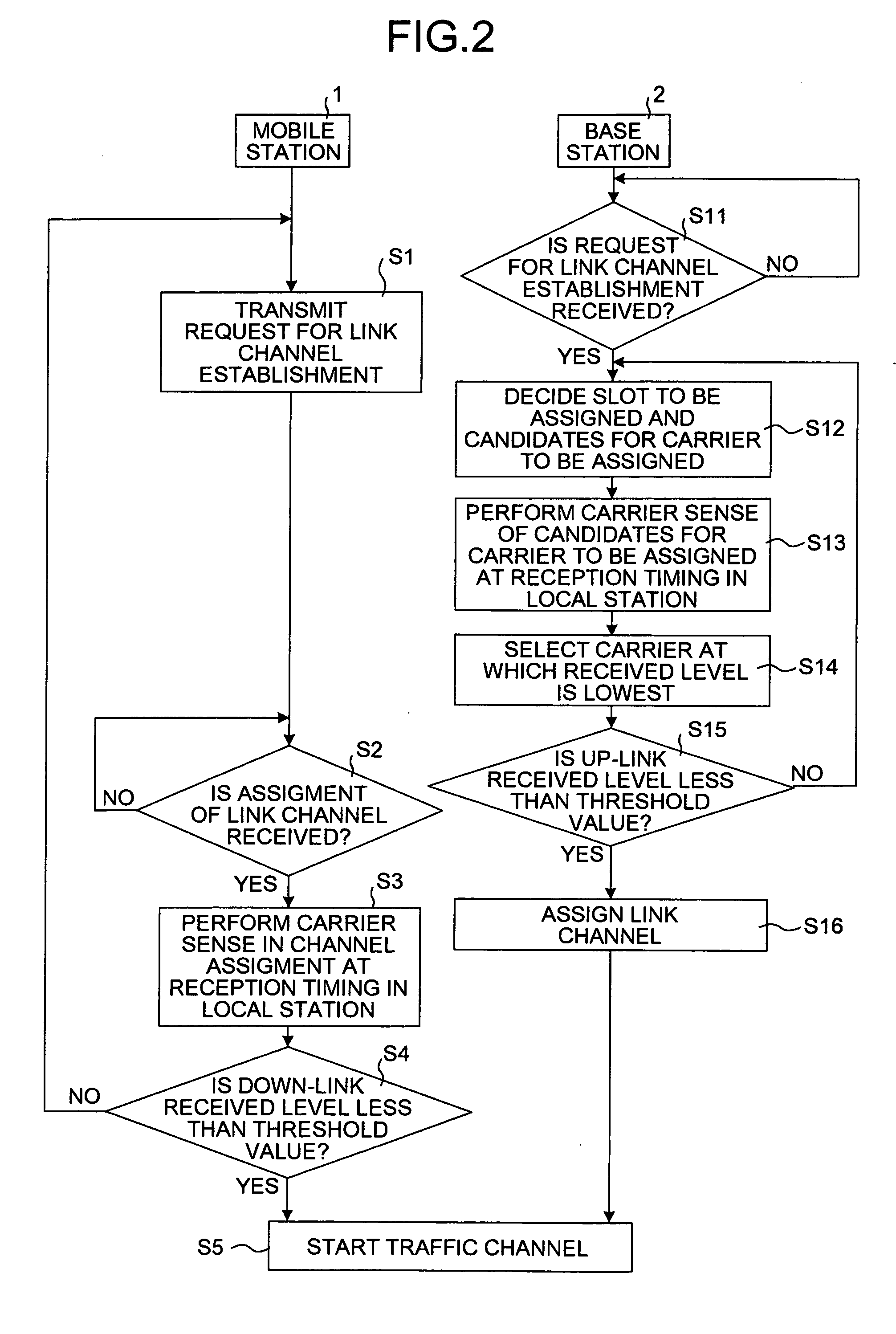
[0037]FIG. 6 is a flowchart of a specific example of the process at step S12 according to the first embodiment as explained above, in other words, the process of deciding a slot to be assigned using the frequency management tables. The detailed process at step S12 is explained below.
[0038] At first, when receiving a request for link channel establishment from the mobile station 1, the base station 2 sets a carrier sense level to “#1” that is the lowest level, to decide a slot to be assigned. The carrier sense level is used for comparison with each received level at carriers in the frequency management tables (see FIG. 3). Then, the base station 2 sets a frequency group that is initially referred to of the frequency management tables, as a frequency group with the highest priority (step S21). Here, an initial carrier sense level is set to “#1”, but the level may be set to any other level accordi...
third embodiment
[0048] A channel assignment method according to the present invention is explained below.
[0049]FIG. 9 is a flowchart of a specific example of the process at step S12 according to the first embodiment, i.e., the process of deciding a slot to be assigned using the frequency management tables. It is noted that processes the same as these of the second embodiment are assigned the same step numbers, and explanation thereof is omitted. Only the processes different from the second embodiment are explained below.
[0050] If at least one of the received levels at carriers as comparison targets in idle slots is below the set carrier sense level (step S23, Yes), the base station 2 stores one or more slots each having a carrier as a comparison target at which the received level is below the set carrier sense level (step S41). If there is one slot stored (step S42, No), the base station 2 decides the slot as a slot to be assigned (step S26). If there is a plurality of slots stored (step S42, Yes)...
PUM
 Abstract
Description
Claims
Application Information
 - R&D
- Intellectual Property
- Life Sciences
- Materials
- Tech Scout
- Unparalleled Data Quality
- Higher Quality Content
- 60% Fewer Hallucinations
Browse by: Latest US Patents, China's latest patents, Technical Efficacy Thesaurus, Application Domain, Technology Topic, Popular Technical Reports.
© 2025 PatSnap. All rights reserved.Legal|Privacy policy|Modern Slavery Act Transparency Statement|Sitemap|About US| Contact US: help@patsnap.com


