
Movable device and receiver device for detecting contacts with the movable device

a technology of moving devices and receiver devices, applied in the field of moving devices, can solve the problems of large error margin, inability to meet requirements, and inability to achieve, and achieve the effect of simple and low-cost receiver devices, free from maintenance, and accurate and/or the range to be detected

Inactive Publication Date: 2007-03-15
CAIROS TECH
View PDF15 Cites 113 Cited by
  • Summary
  • Abstract
  • Description
  • Claims
  • Application Information

AI Technical Summary

Benefits of technology

[0029] By setting the predetermined time duration in the receiver devices worn, or carried, by the player, it is thus possible to set the accuracy and / or the range to be detected. For this purpose, no access to the ball itself is required.
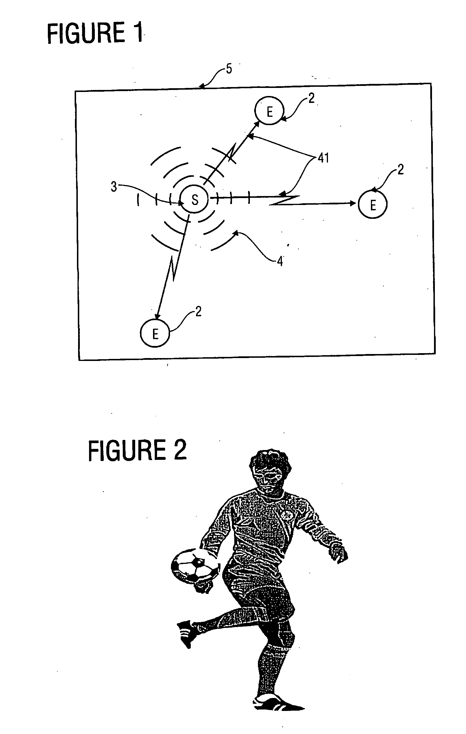
[0030] In addition, the use of two signals of different speeds allows to dispense with any complicated and, thus, failure-prone electronics in the ball itself. One only needs to make sure that the ball has a proximity detector which operates in a contact-controlled or non-contact manner and which will then control the transmission of the two signals of different delay times. Thus, no complicated electronics are required within the ball itself, which is a considerable advantage in particular since the forces and accelerations acting on the ball may be huge, so that there is a very rough environment for there to be an electronic system within the ball.
[0031] On the receiver side, no personal identification or the like is required, which is of considerable advantage -particularly if one considers that what is dealt with here is a mass product, i.e. that may players are to be provided with receiver devices—since thus, all receiver devices may operate in an identical manner and do not require any specific identification, which also renders the receiver devices simple and low in or even completely free from maintenance. In addition, a simple and robust structure also ensures safety from tampering.

Problems solved by technology

The technical means employed so far—mainly cameras—either completely fail to meet the requirements set forth above, or meet them only to an insufficient degree; also the methods, hitherto known, for position finding by means of various transmitter and receiver combinations still leave a large error margin with regard to the spatial resolution of the position indication, with regard to the ease of use of the transmitter / receiver components required, and above all with regard to evaluating the data obtained by means of the transmitter / receiver system, so that it is not yet possible, or at least requires a large amount of effort, to evaluate the results obtained from this data as fast as possible.

Method used


Image

  • Movable device and receiver device for detecting contacts with the movable device
  • Movable device and receiver device for detecting contacts with the movable device
  • Movable device and receiver device for detecting contacts with the movable device

Examples


Embodiment Construction

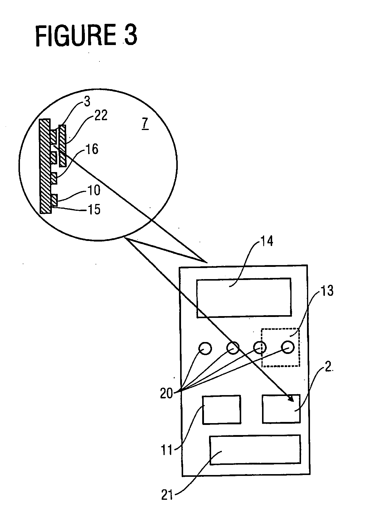
[0040] To improve one's skills in a ball game or to be able to compare oneself to other players, objective data must be obtained in a simple manner. This data must be visualized such that a training feedback or a comparison to other players is possible. To this end, respective components are provided within the game device, and, if need be, a data detection device including a display unit is provided.

[0041] In a low-cost system, recognition of a person cannot be effected via delay times of the radio signals. To this end, the incoming radio signals would have to be compared to a highly accurate time reference. Also, a network would have to be built within which all times measured are compared to determine that player who is closest to the ball. Therefore, one concludes, from the transmission of a radio signal and an acoustic signal, as to who had the last ball contact.

[0042] By measuring the forces acting on the game device, one may also infer the shot force or the rotational speed...


PUM


Abstract

The movable device includes a detector for detecting that an object is located in the vicinity of or at the movable device, as well as a transmitter module for transmitting two signals having different signals speeds. These two signals are received by a receiver, the receiver having a detector to ascertain whether the second signal arrives within a predetermined time period as of reception of the first signal, so as to provide, when this has been detected, a detector signal indicating that the movable device has been contacted by the object. Exemplary movable devices are game devices such as footballs. Exemplary objects are arms, legs, football shoes, rackets, bats, etc.

Description

CROSS REFERENCE TO RELATED APPLICATION [0001] This application claims priority from German Patent Application No. 102005036355.5, which was filed on Jul. 29, 2005, and is incorporated herein by reference in its entirety. BACKGROUND OF THE INVENTION [0002] 1. Field of the Invention [0003] The present invention relates to movable devices and in particular to game devices such as balls, and to concepts for detecting any contact of an object with the movable device. [0004] 2. Description of Prior Art [0005] For quite some time, various interest groups have wished to study and understand the sequence of movements of moving objects and / or persons, which requires an exact indication of the object's position in space and time. What is of particular interest here are, among other things, game balls, in particular in commercialized types of sport, such as footballs, or soccer balls, which are highly accelerated in three-dimensional space, as well as tennis or golf balls. The question of who w...

Claims


Application Information

Patent Timeline
Patent Type & Authority Applications(United States)
IPC IPC(8): A63B43/06
CPCA63B41/00A63B43/00A63B69/002A63B71/0605A63B2220/40G01S13/862A63B2225/30A63B2225/50A63B2225/52G01S13/74A63B2220/833
Inventor KUENZLER, UDOENGLERT, WALTER
Owner CAIROS TECH
Learn More