Method and apparatus for storing and protecting conduit

a conduit and conduit technology, applied in the field of conduit managers, can solve problems such as safety hazards and user frustration, cords posing frustration and safety hazards to users, hazards to the area and the device, etc., and achieve the effect of overcompensating deficiencies and inadequacies

Inactive Publication Date: 2007-03-22
STOEPPELWERTH PAUL B
View PDF23 Cites 2 Cited by
  • Summary
  • Abstract
  • Description
  • Claims
  • Application Information

AI Technical Summary

Benefits of technology

[0007] The present invention overcomes the deficiencies and inadequacies of the prior art by providing a manifold to gather, store, and protect conduit. In one exemplary embodiment, the present invention affords the user a manifold or housing, which receives a power strip and includes a means for gathering and storing the related electrical cords. The manifold may be constructed of a fire-resistant material, such as a rigid, molded plastic, for safety.

Problems solved by technology

A common problem of clustering such cords or hoses includes safety hazards and user frustration.
The mass of cords pose issues of frustration and safety to users, and hazards to the area and the devices.
The problem sought to be solved there appears to be limited to preventing a small child from accessing electrical plugs and outlets.
However that apparatus does not organize or store the excess conduit.
However these flexible packs do not provide a supply or surge protector nor do they provide a sturdy device suitable for vigorous use.
Therefore, no known solution teaches one structure for gathering, organizing, and storing a plurality of conduits and a power strip or surge protector in a housing providing a protective cover that allow for vigorous use.

Method used


Image

  • Method and apparatus for storing and protecting conduit
  • Method and apparatus for storing and protecting conduit
  • Method and apparatus for storing and protecting conduit

Examples


Embodiment Construction

[0015] As required, detailed embodiments of the present invention are disclosed herein. It will be understood that the disclosed embodiments are merely examples to illustrate aspects of the invention that may be embodied in various and alternative forms. The figures are not necessarily to scale, and some features may be exaggerated or minimized to show details of particular components. In other instances, well-known materials or methods have not been described in detail to avoid obscuring the present invention. Therefore, specific structural and functional details disclosed herein are not to be interpreted as limiting, but as a basis for the claims and for teaching one skilled in the art to variously employ the present invention.

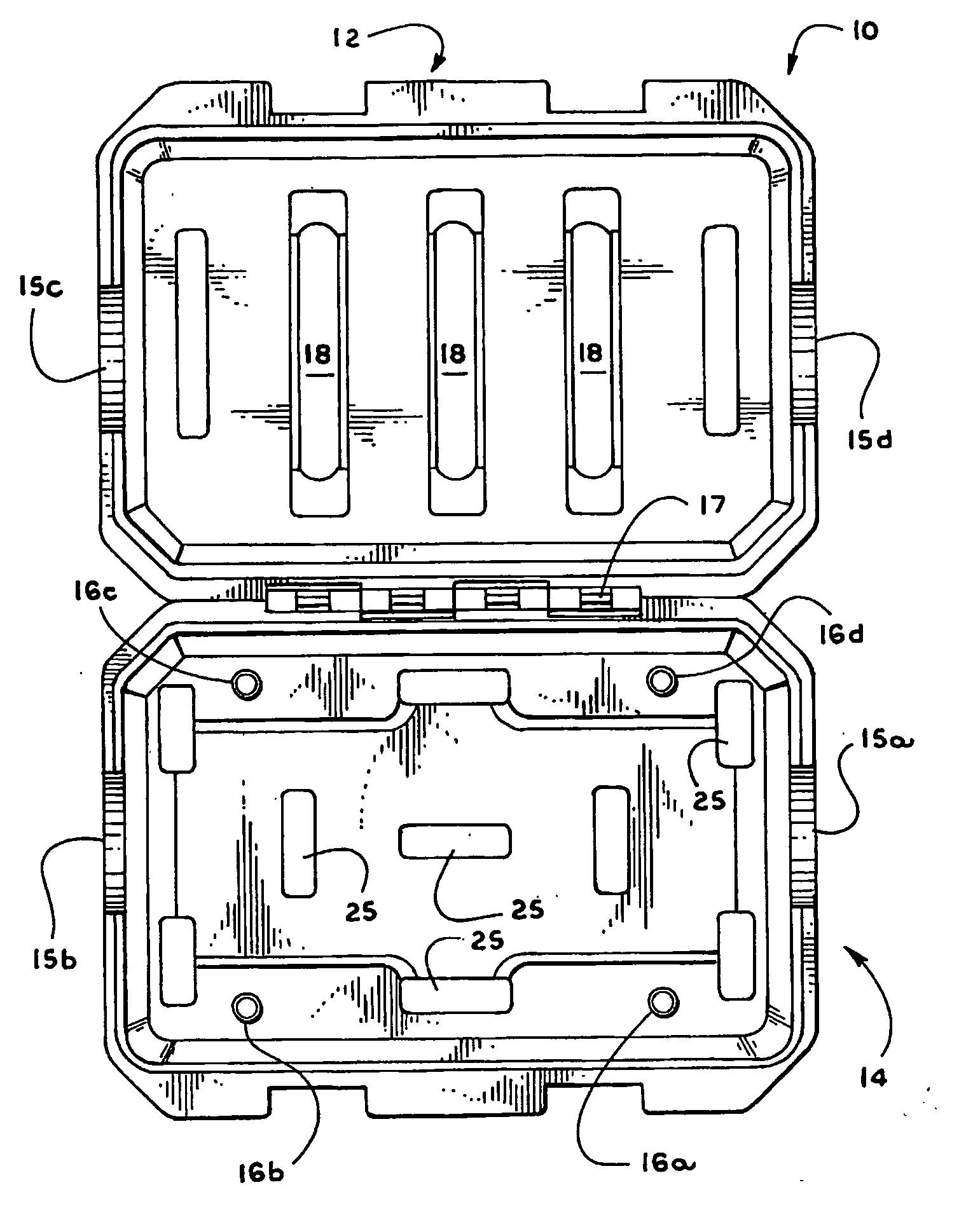
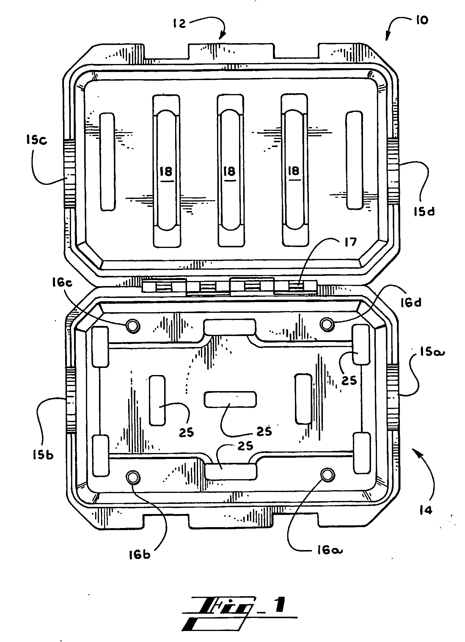
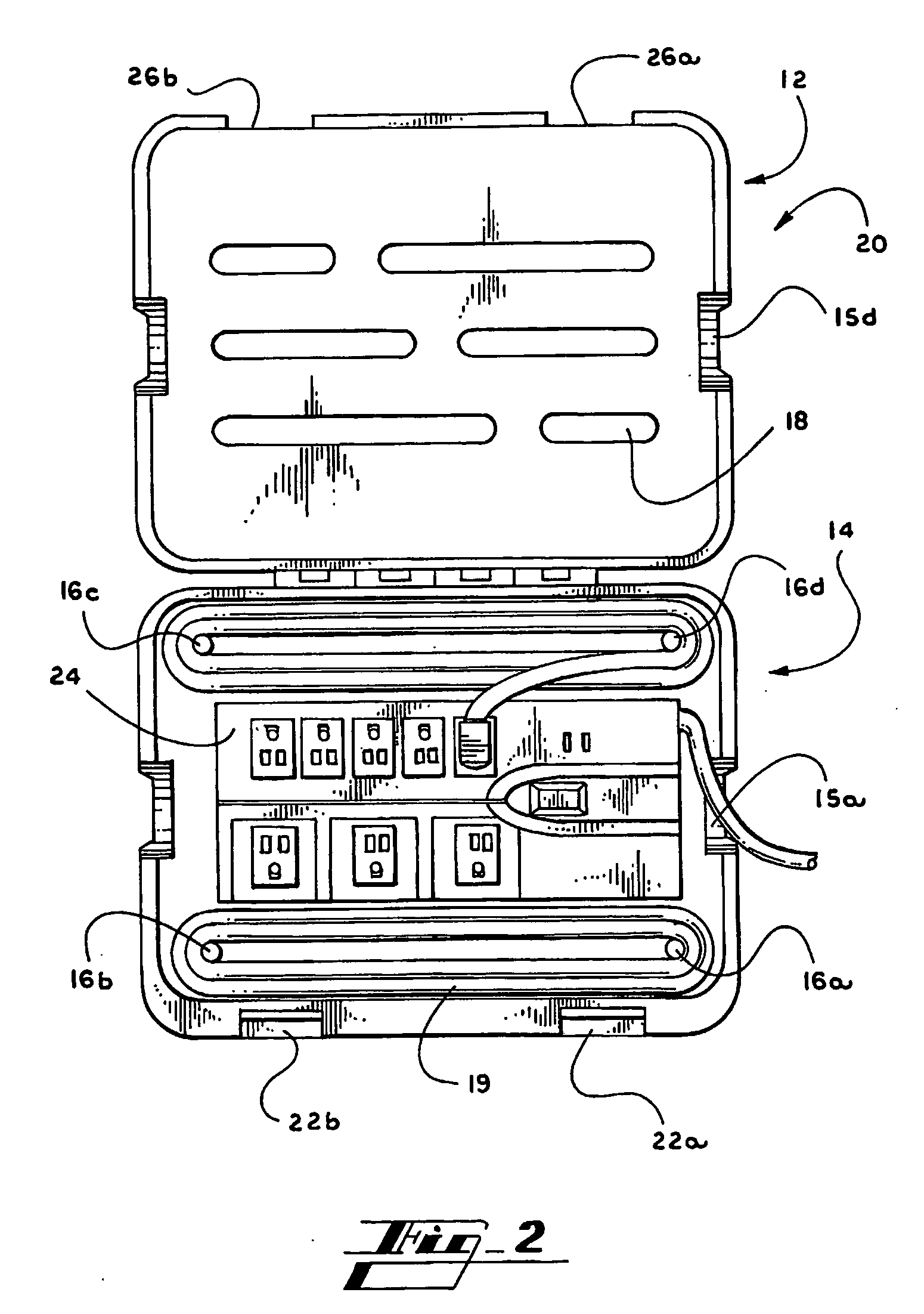
[0016] Referring now to the drawings in which like numerals indicate like elements throughout the several views, the drawings illustrate various aspects of exemplary embodiments of a conduit-receiving manifold according to the teachings of the present inven...


PUM


Abstract

Taught herein is a manifold (10) for housing and outlet (24) and related conduit (19). The manifold (10) provides a means for gathering, storing and protecting excess conduit associated with the outlet and the conduit connected to the outlet (16). The manifold includes conduit apertures (15) to allow conduit to ingress and egress the manifold. The manifold may also include ventilation apertures (18) to allow airflow. The manifold may (10) be a clam-shell style housing, with hingedly attached top and bottom portions (12, 14). Additionally, the manifold may be made of a fire-resistant material and may include a locking device (22) to secure the manifold in a closed condition. The present invention also teaches the method of gathering, storing and protecting an outlet and related excess conduit within a ventilated manifold.

Description

FIELD OF THE INVENTION [0001] The present invention relates to a conduit manager, and, more particularly, to a receiving manifold with a conduit manager that gathers, stores and protects the conduit while providing a protective cover over the connection points at the manifold, such as the electrical cords, plugs and structure associated with a power supply strip. BACKGROUND OF THE INVENTION [0002] Many different environments call for conduit being directed to and collected at a manifold. Conduit such as electrical cords, medical tubing, plumbing, pneumatics and the like are routed to and from the necessary devices, and often converge at junctures and terminals. A common problem of clustering such cords or hoses includes safety hazards and user frustration. [0003] For example, it is all too common that a power supply at a home office is simply a mass of cords plugged into a power strip, including those having two-prong plugs, grounded plugs, transformers and the like. The cords from ...

Claims


Application Information

Patent Timeline
Patent Type & Authority Applications(United States)
IPC IPC(8): H02J3/14B65H75/16H01R13/72H02G11/02
CPCB65H75/16H01R13/533H01R25/006H01R13/72H01R13/6397
Inventor STOEPPELWERTH, PAUL B.
Owner STOEPPELWERTH PAUL B
Why Eureka
Try Eureka