Receiving frame having removable computer drive carrier and fan modules

a computer drive carrier and fan module technology, applied in the direction of electrical apparatus casings/cabinets/drawers, instruments, cooling/ventilation/heating modifications, etc., to achieve the effect of thin space-conserving profile and easy removal

Inactive Publication Date: 2007-03-22
PAUL DIETER G +1
View PDF4 Cites 57 Cited by
  • Summary
  • Abstract
  • Description
  • Claims
  • Application Information

AI Technical Summary

Benefits of technology

[0007] In general terms, a U-shaped receiving frame is disclosed that is mounted in a computer drive bay to be interfaced with a host computer. The receiving frame is adapted to slidably receive a removable computer drive carrier module and a removable fan module. The computer drive module encloses a conventional computer (e.g., disc) drive, and the fan module exhausts heat generated by the computer drive to the atmosphere. To this end, the removable drive carrier module and the removable fan module are efficiently stacked one above the other to create a relatively thin space-conserving profile. The removable drive carrier module may be pulled outwardly from the receiving frame and swapped for a different module. Should the fan module fail, it may be simply and easily removed from the receiving frame and replaced with a new module, but without affecting the computer drive or requiring that the receiving frame be taken out of service.

Problems solved by technology

Moreover, the receipt of the tab through the window creates a stop to block the removal of the computer drive carrier module from the receiving frame.

Method used


Image

  • Receiving frame having removable computer drive carrier and fan modules
  • Receiving frame having removable computer drive carrier and fan modules
  • Receiving frame having removable computer drive carrier and fan modules

Examples


Embodiment Construction

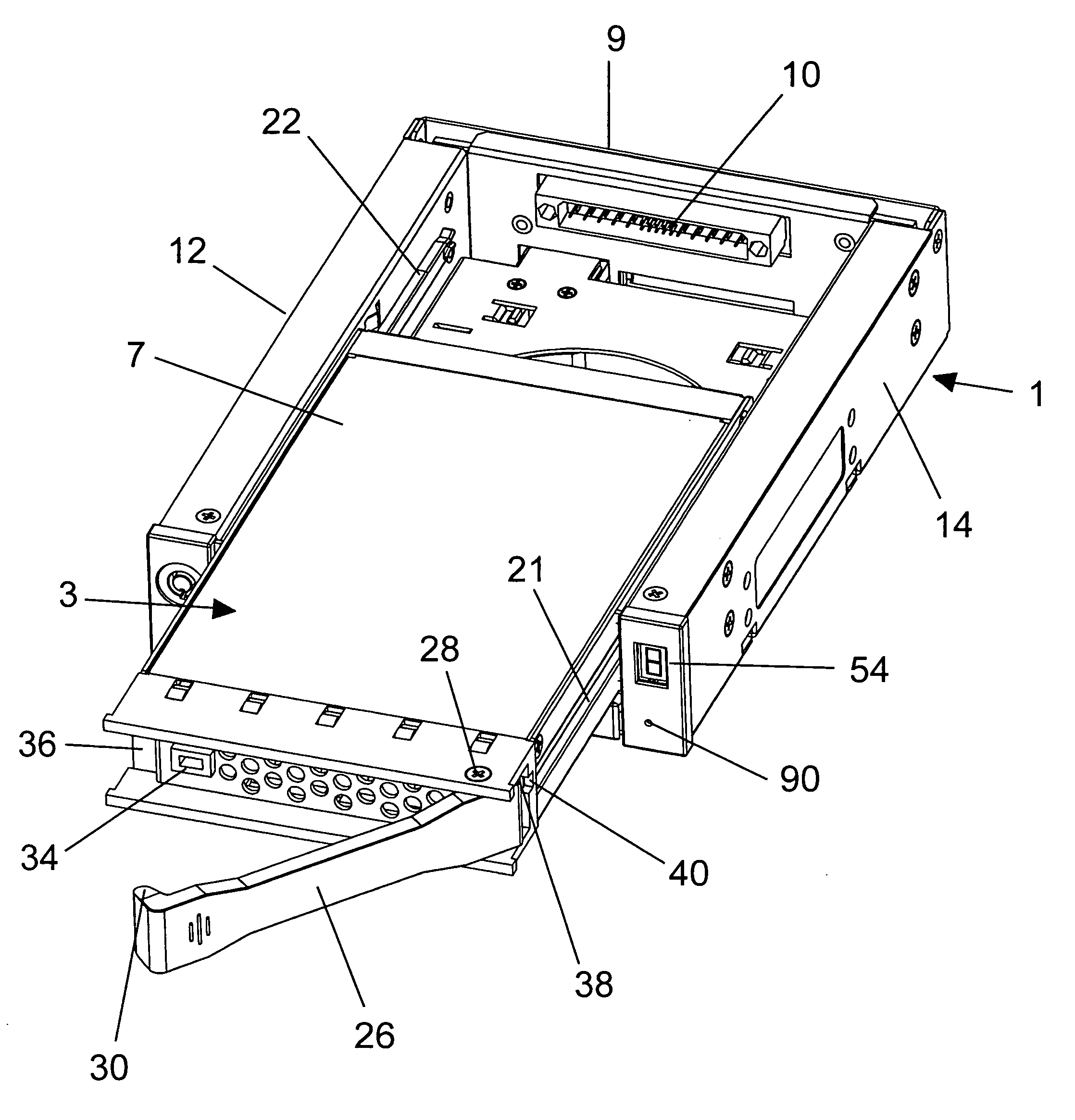
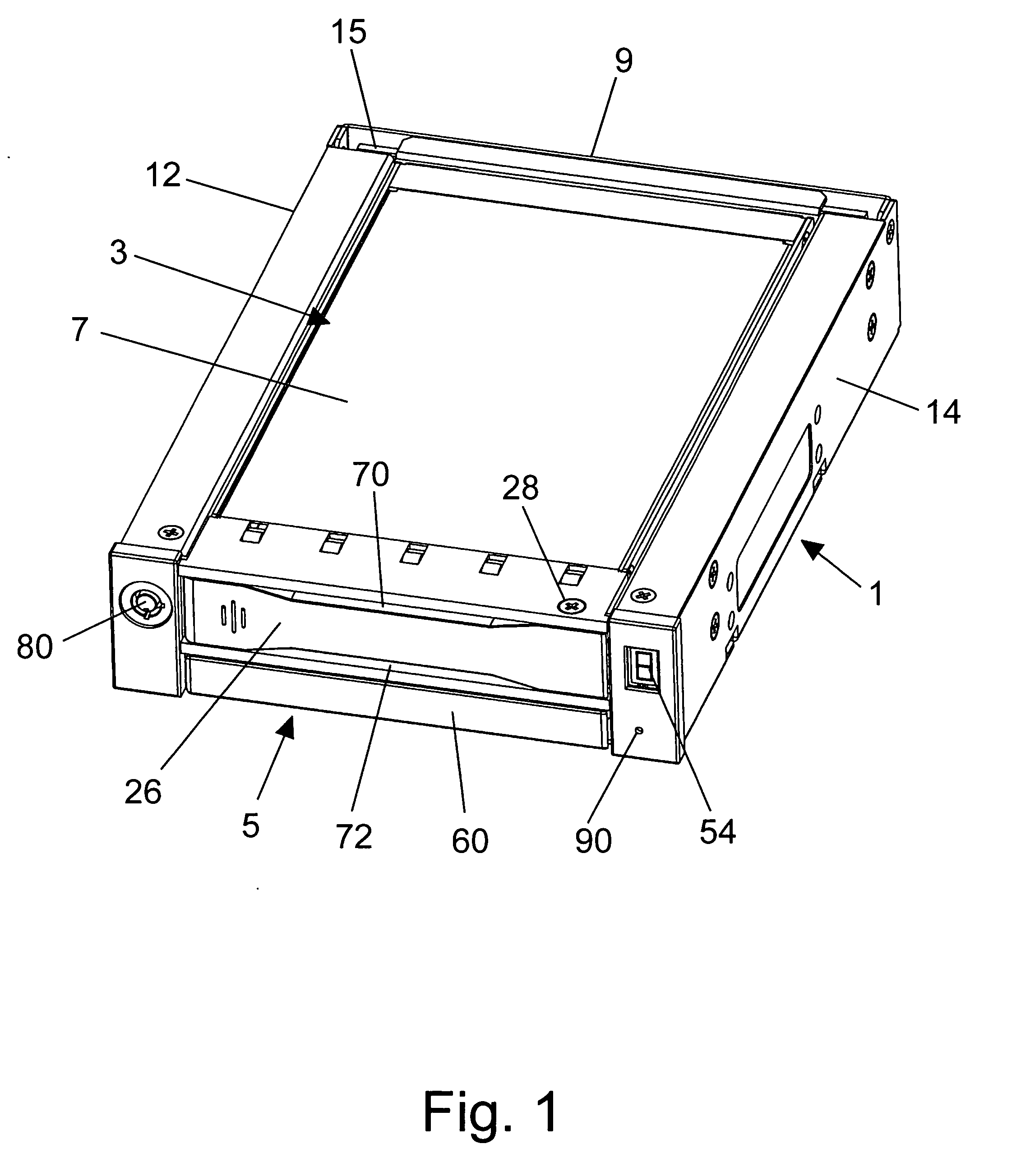
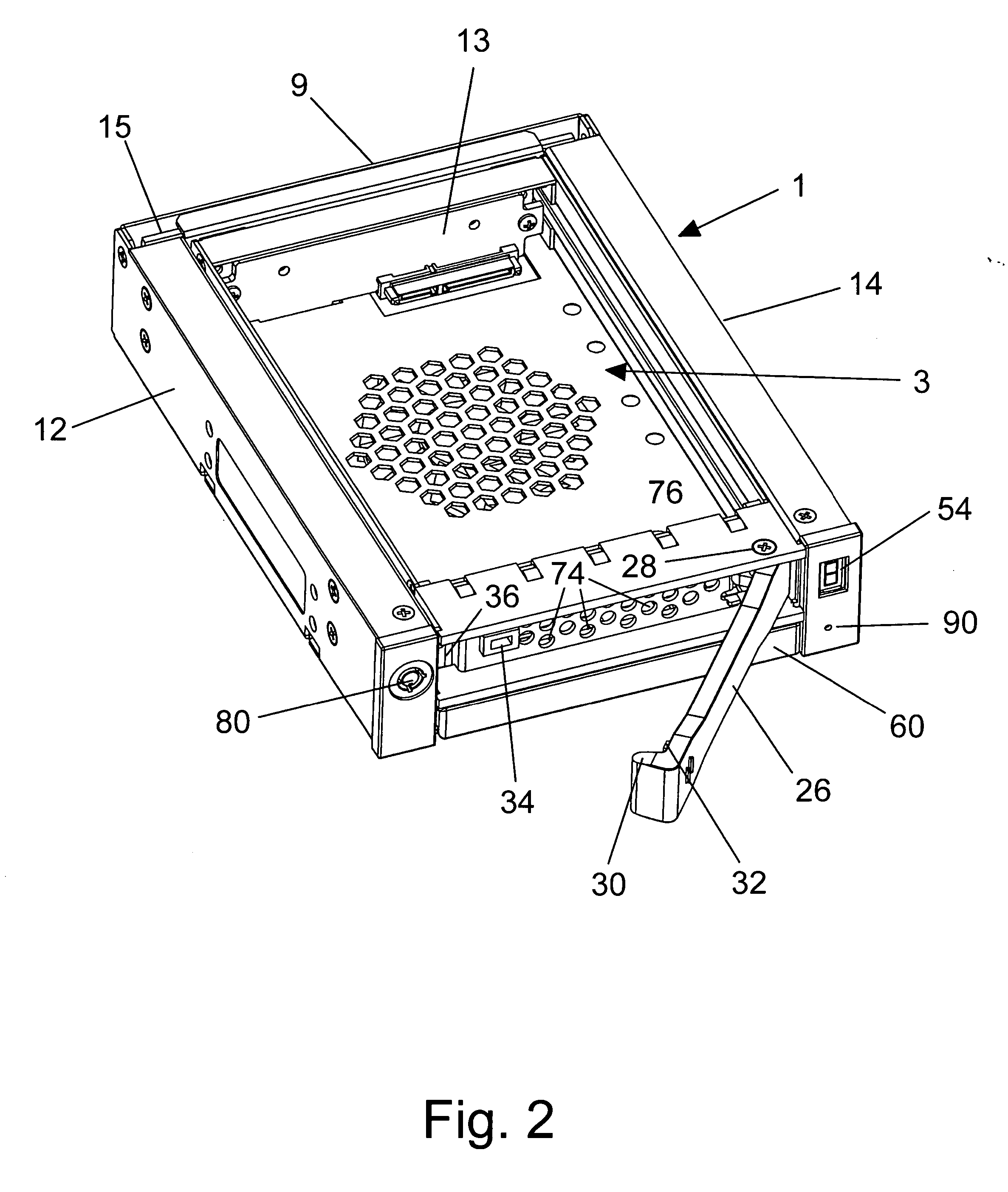
[0021] Referring initially to FIGS. 1-7 of the drawings, there is shown a U-shaped receiving frame 1 for receiving therewithin a removable computer drive carrier module 3 and a removable fan module 5. The drive carrier module 3 encloses a standard computer drive (not shown), such as a disk drive, or the like. The U-shaped receiving frame 1 is typically mounted in a computer drive bay or similar enclosure (also not shown) by which the computer drive that is enclosed within drive carrier module 3 can be interfaced with a host computer. In the case of FIGS. 1, 4 and 5, a cover 7 of the drive carrier module 3 is shown positioned over top the computer drive. In the case of FIG. 2, the top cover 7 and the computer drive have been removed from the drive carrier module 3.

[0022] As will be explained in greater detail hereinafter, each of the removable drive carrier module 3 and the removable fan module 5 is slidable into and out of the U-shaped receiving frame 1. As is best shown in FIG. 7 ...


PUM


Abstract

A (e.g., U-shaped) receiving frame to be mounted in a drive bay or similar enclosure and interfaced with a host computer. The receiving frame receives therewithin a removable computer drive carrier module which encloses a computer drive and a removable fan module which exhausts heat generated by the computer drive to the atmosphere. Should the fan module fail, it is simply and easily removed from the receiving frame to be replaced by a new module, but without affecting the operation of the computer drive module or requiring that the receiving frame be taken out of service. A rotatable handle is pivotally connected across the first end of the computer drive carrier module. When the computer drive module is installed in the receiving frame, the handle is rotated to a closed position by which to cause power to be supplied to the computer drive. When it is desirable to apply a pulling force to the handle in order to remove the computer drive carrier from the receiving frame, the handle is rotated to an open position by which to cause power to be automatically removed from the computer drive.

Description

BACKGROUND OF THE INVENTION [0001] 1. Field of the Invention [0002] This invention relates to a (e.g., U-shaped) receiving frame that is adapted to be interfaced with a host computer and to receive therewithin a removable computer drive carrier module which encloses a computer drive and a removable fan module which exhausts heat generated by the computer drive to the atmosphere. Should the fan module fail, it is simply and easily removed from the receiving frame to be replaced with a new module, but without effecting the operation of the computer drive module or requiring that the receiving frame be taken out of service. [0003] 2. Background Art [0004] With the advent of personal computers and workstations, it is often necessary to remove the medium on which computer data is stored. For example, it may be desirable to remove a storage medium so as to be carried to a different site and / or a different computer system. It may also be desirable to remove the storage medium to a secure l...

Claims


Application Information

Patent Timeline
Patent Type & Authority Applications(United States)
IPC IPC(8): G06F1/20G06F1/16
CPCG06F1/20G06F1/187
Inventor PAUL, DIETER G.TANG, CHOON-TAK
Owner PAUL DIETER G
Why Eureka
Try Eureka