

Electric potential measuring apparatus electrostatic capacitance measuring apparatus, electric potential measuring method, electrostatic capacitance measuring method, and image forming apparatus
a technology of electrostatic capacitance and measuring apparatus, applied in the direction of electrographic process, specific gravity measurement, instruments, etc., can solve the problem of increasing the number of constituent components
- Summary
- Abstract
- Description
- Claims
- Application Information
AI Technical Summary
Problems solved by technology
Method used
Image

Examples
first embodiment
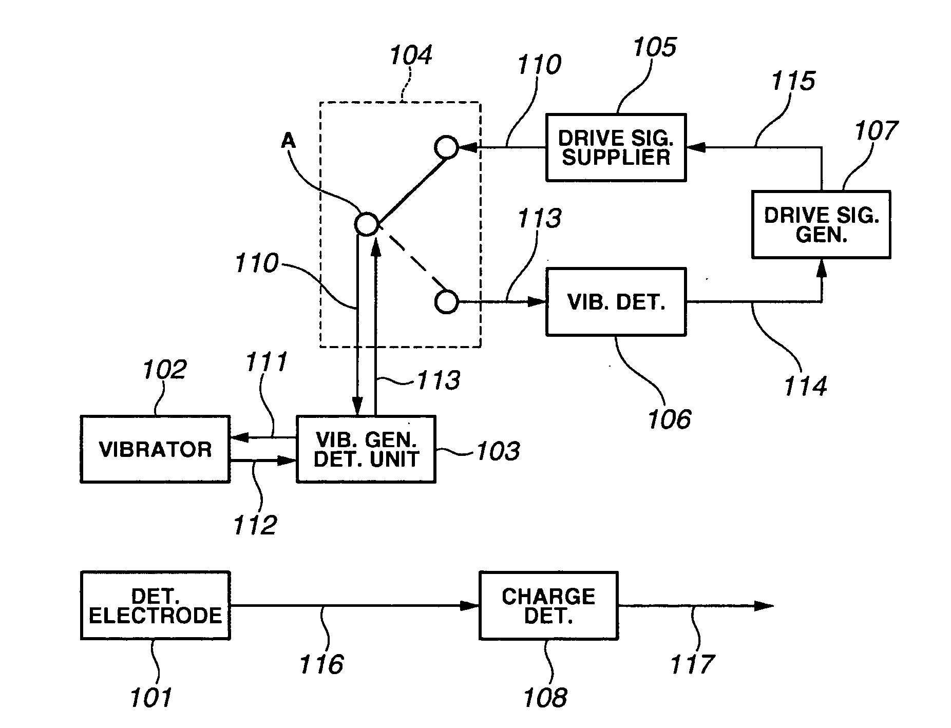
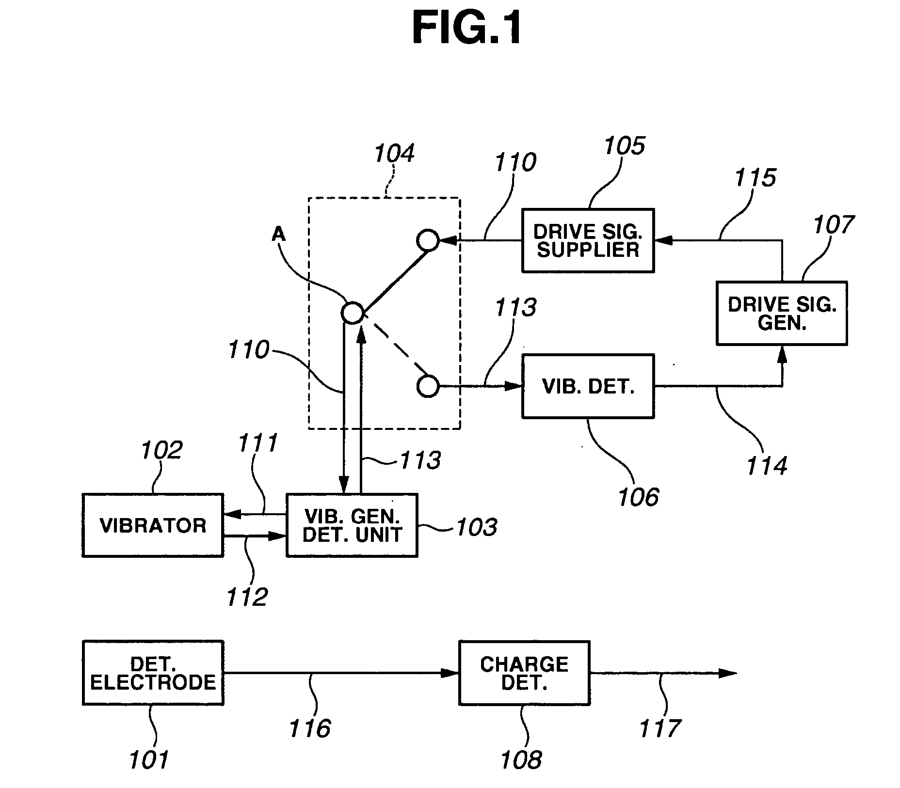
[0033] As illustrated in FIG. 1, the apparatus of the first embodiment includes the detecting electrode 101, and the vibrator 102. As the vibration generating-detecting unit 103 (the vibration generator), there is also arranged an electromechanical converting unit 103 that excites the vibration of the vibrator 102, and detects the condition of the vibration of the vibrator 102. Here, the electromechanical converting unit includes not only a unit for converting electric energy into mechanical energy, but also a unit for converting mechanical energy into electric energy. An example of the electromechanical converting unit is a piezoelectric device.
[0034] In the apparatus, there are further arranged a wiring changing unit 104, such as a switch, a driving signal supplier 105, such as a driving circuit for generating a driving signal for driving the vibrator 102, a vibration detector 106, such as a detecting circuit for detecting the condition of the vibration of the vibrator 102, and a ...
second embodiment
[0049] In the second embodiment, an electromagnetic actuator is used as the vibration generating-detecting unit 103 (the vibration generator). FIGS. 4A and 4B illustrate two types of vibration generating-detecting units 103, respectively. In FIGS. 4A and 4B, reference numeral 211 designates a vibrator. Reference numeral 212 designates a support frame. Reference numeral 213 designates a torsion bar or spring. Reference numeral 214 designates a pair of pads for the detecting electrodes 101. Reference numeral 215 designates an electric wire. Reference numeral 216 designates a pair of permanent magnets. Reference numeral 217 designates a coil. Reference numeral 218 designates a pad for the coil 217. Reference numeral 219 designates a substrate for supporting the coil 217.
[0050] The vibrator 211 is rotatably supported by the torsion bar 213, which is fixed to the support frame 212. The detecting electrodes 101 are arranged on the vibrator 211. The electric wire 215 is disposed on the vib...
third embodiment
[0059]FIGS. 5A and 5B show two types of operations of the wire changing unit 104 in the electric potential measuring apparatus of the The abscissa indicates time, and the ordinate indicates the magnitude of the signal.
[0060] In FIG. 5A, the detecting period is set longer than the driving period. Specifically, a ratio between the driving period and the detecting period is set at 1:3. In this construction, the period for detecting the condition of the vibration can be elongated. Accordingly, even when the detection signal 113 of the vibration condition is small, the condition of the vibration can be accurately detected.
[0061] In FIG. 5B, the detecting period is set shorter than the driving period. Specifically, a ratio between the driving period and the detecting period is set at 3:1. In this construction, the period for supplying the driving signal 110 to the vibration generating-detecting unit 103 is increased. Accordingly, the driving signal 110 supplied during the driving period...
PUM
| Property | Measurement | Unit |
|---|---|---|
| electric potential | aaaaa | aaaaa |
| electrostatic capacitance | aaaaa | aaaaa |
| mechanical vibration | aaaaa | aaaaa |
Abstract
Description
Claims
Application Information