Dot head and method of manufacturing armature structure for dot head

a technology of armature structure and dot head, which is applied in the field of dot head, can solve the problems of troublesome subjecting pure iron to carburization processing, and achieve the effects of high printing speed, excellent durability and high magnetic permeability

Active Publication Date: 2007-03-22
TOSHIBA TEC KK
View PDF30 Cites 21 Cited by
  • Summary
  • Abstract
  • Description
  • Claims
  • Application Information

AI Technical Summary

Benefits of technology

[0009] An object of the invention is to provide a dot head which realizes high speed printing and excellent durability and also to provide a method of manufacturing an armature structure which is used for the dot head and has a high magnetic permeability and excellent durability.

Problems solved by technology

However, it is very troublesome to subject the pure iron to the carburization processing, and the pure iron having been subjected to the carburization processing leaves much to be improved in efficiency such as a magnetic permeability and durability.

Method used


Image

  • Dot head and method of manufacturing armature structure for dot head
  • Dot head and method of manufacturing armature structure for dot head
  • Dot head and method of manufacturing armature structure for dot head

Examples


Embodiment Construction

[0021] An embodiment of the invention will be explained in detail with reference to the accompanying drawings.

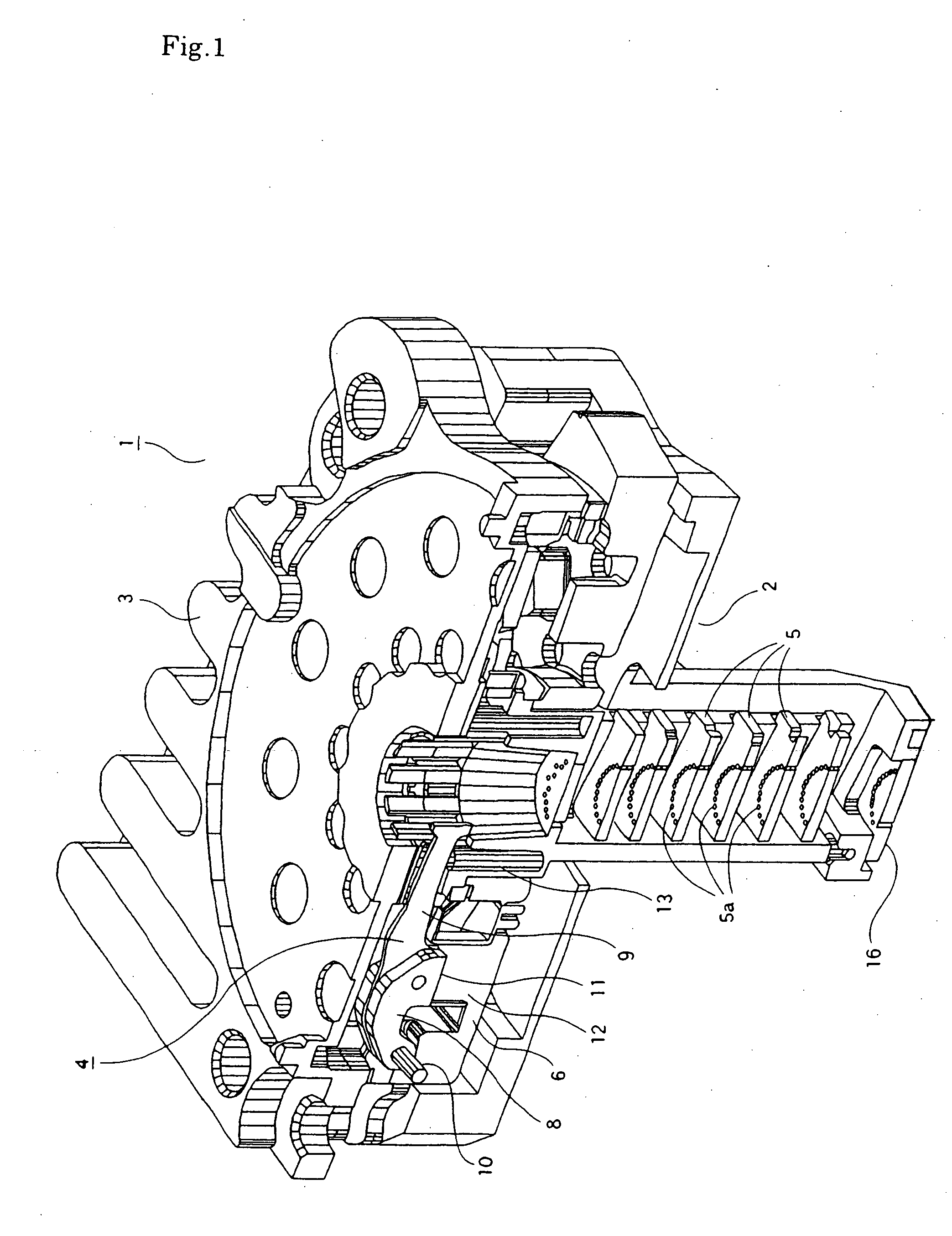
[0022] First, the explanation will be made with reference to FIG. 1 as to the entire configuration of the dot head of a wire dot printer. FIG. 1 is a perspective sectional view schematically showing the dot head 1, in which the dot head is cut longitudinally along the center portion thereof.

[0023] The dot head 1 includes a front casing 2 and a rear casing 3 which are coupled by attachment screws (not shown) Armature structures 4, wire (needle) guides 5 and yokes 6 etc. are provided between the front casing and the rear casing.

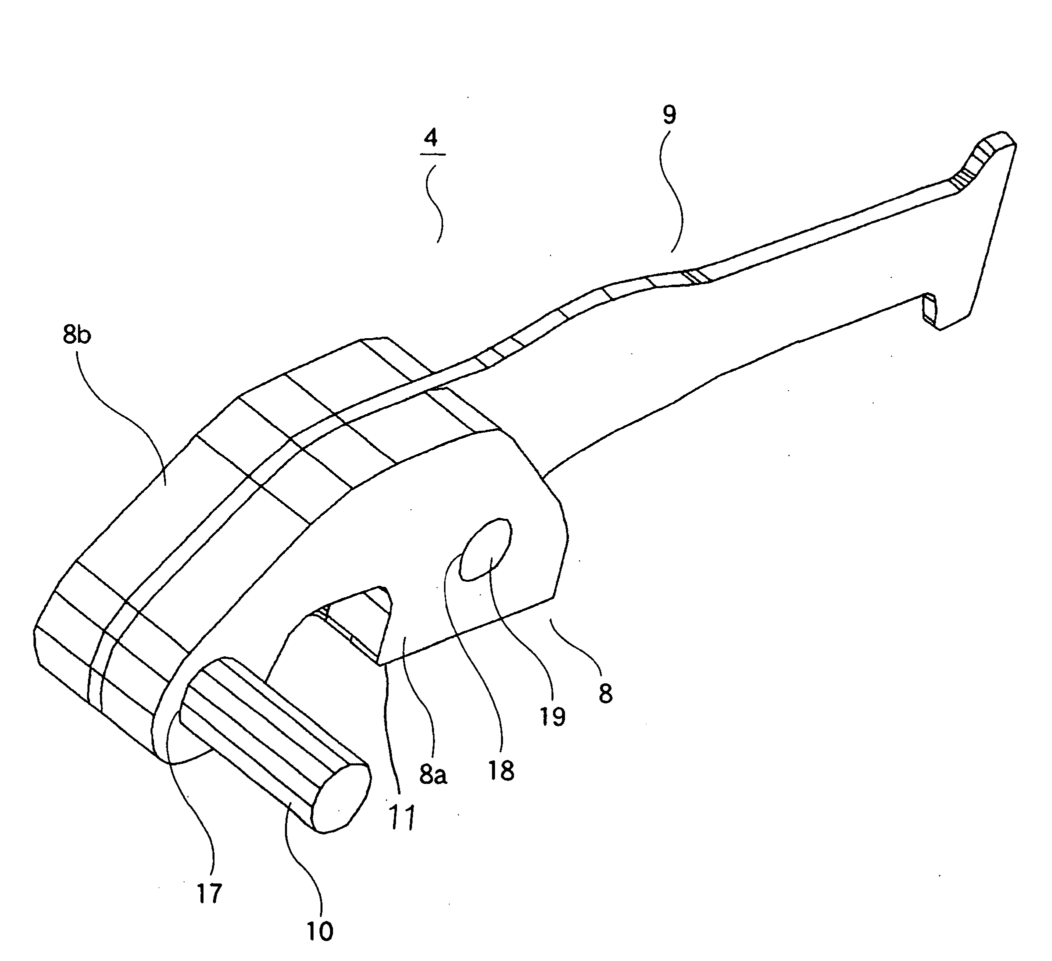
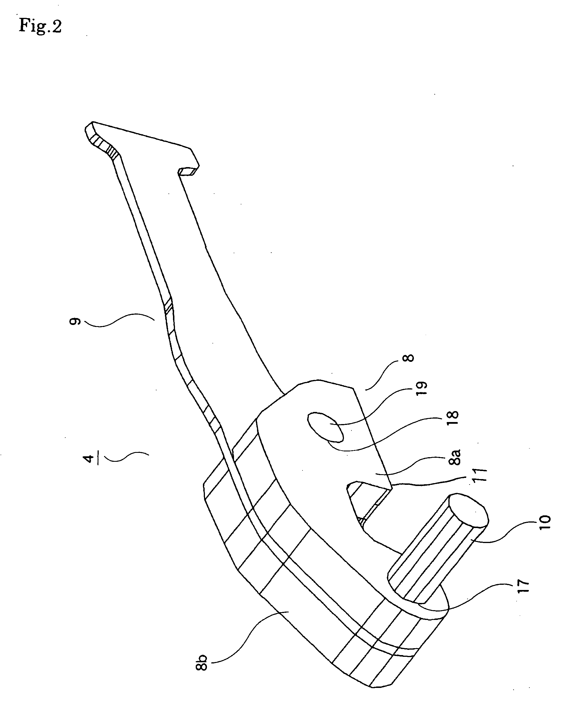
[0024] The armature structure 4 includes, although the detailed structure thereof is described later, an armature 8 and an arm 9 extended from the free end (the right end in the figure) of the armature 8. The armature 8 is provided with a fulcrum shaft 10 near the one end (the left end in the figure) thereof so as to be rotatable therearound in a man...


PUM


Abstract

According to a dot head of the invention, an armature structure for moving a printing needle forward and backward has the efficiency that the magnetic characteristics is excellent and mechanical intensity is high. The armature structure is manufactured in a manner that an arm member, which is formed by subjecting a plate-shaped material excellent in abrasion resistance performance and having a high intensity to a plating processing using born etc., is sandwiched at a portion thereof from both sides in a stacked manner by two armature members each of which is formed by subjecting a plate-shaped material excellent in magnetic characteristics to a plating processing using born etc. A pin formed by subjecting a piano wire to a plating processing using boron etc. is inserted with a small pressure into common through holes of the two armature members and the arm member thus stacked thereby to provisionally assemble them. A pair of electrodes are made in contact to the portions including the slightly-pressed-in pin near the pin of the provisionally assembled two armature members and the arm member, and a current is supplied to the electrodes in a state that the portions are sandwiched by the electrodes thereby to melt and harden the plated portions using boron etc. to integrate the two armature members and the arm member.

Description

CROSS-REFERENCE TO RELATED APPLICATION [0001] This application is based upon and claims the benefit of priority from prior Japanese Patent Application No. 2005-276588 filed on Sep. 22, 2005, the entire contents of which are incorporated herein by reference. BACKGROUND OF THE INVENTION [0002] 1. Field of the Invention [0003] The present invention relates to a dot head for driving the needle of a wire dot printer and a method of manufacturing the armature structure for the dot head. [0004] 2. Description of the Related Art [0005] The wire dot printer is arranged to move a printing wire (hereinafter, simply referred to as a wire) called a needle forward and backward to strike the tip end of the wire against a print medium thereby to print a dot-shaped image thereon. Since the wire dot printer employs such the printing method, the wire dot printer can simultaneously print plural slips etc. in a stacked state and so is employed for business use. Although there are various kinds of method...

Claims


Application Information

Patent Timeline
Patent Type & Authority Applications(United States)
IPC IPC(8): B41J2/27
CPCB41J2/27
Inventor KAWAGUCHI, TAKAHIRO
Owner TOSHIBA TEC KK
Why Eureka
Try Eureka