Mechanical mechanism for a sensor-dispensing instrument

a mechanical mechanism and sensor technology, applied in the direction of instruments, apparatus for dispensing discrete objects, material electrochemical variables, etc., can solve the problems of sensor foil bursting or rupturing on the other side, user experience difficulties in operation and/or manipulation of disclosed sensor instruments, etc., to eliminate sensor spoilage, reduce the possibility of jamming, and facilitate operation

Inactive Publication Date: 2007-03-22
BROWN MICHAEL K +2
View PDF20 Cites 11 Cited by
  • Summary
  • Abstract
  • Description
  • Claims
  • Application Information

AI Technical Summary

Benefits of technology

[0015] Accordingly, an object of the present invention is to provide a new and improved sensor dispensing instrument for handling the sensors contained in a sensor pack of multiple sensors used in testing blood glucose. In particular, objects of the present invention are to provide a new and improved fluid sensor dispensing instrument handling device having a mechanical mechanism that can be more easily operated by a user with limited finger strength or dexterity, that reduces the possibility of jams, eliminates the spoilage of sensors because of user error, and which otherwise overcomes the problems or limitations discussed above.

Problems solved by technology

Alternatively, some packages require the user to exert force against one side of the package resulting in the sensor bursting or rupturing the foil on the other side.
As can be appreciated, the opening of these packages can be difficult.
Although the sensor instrument disclosed in the '986 patent overcomes many of the problems discussed above in connection with the use of individual sensors, some users of have experienced difficulties in the operation and / or manipulation of the disclosed sensor instrument.
For example, users with limited dexterity may find the manipulation of the slide latch difficult.
Similarly, some users, elderly users in particular, may find the operation of this device complicated or confusing.
This may lead to user errors in the manipulation of the slide latch, which can result in a jam in the operation of the device.
In addition, some users have encountered spoiled sensors resulting from partial or incorrect manipulation of the device.
If, for example, a user intending to activate the display mode of the device accidentally moves the slide latch into the testing mode direction, the knife blade may puncture the foil covering the sensor cavity of the new sensor.

Method used


Image

  • Mechanical mechanism for a sensor-dispensing instrument
  • Mechanical mechanism for a sensor-dispensing instrument
  • Mechanical mechanism for a sensor-dispensing instrument

Examples


Embodiment Construction

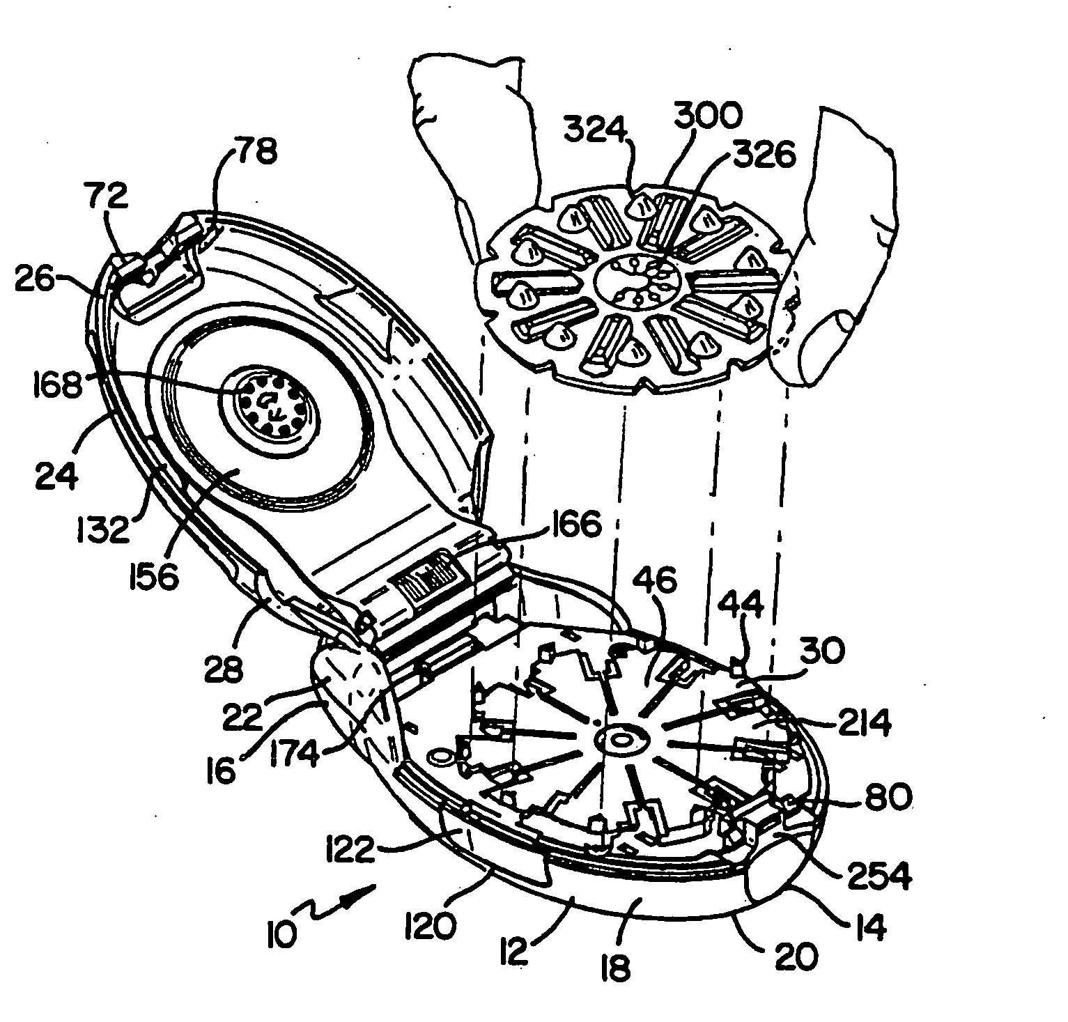
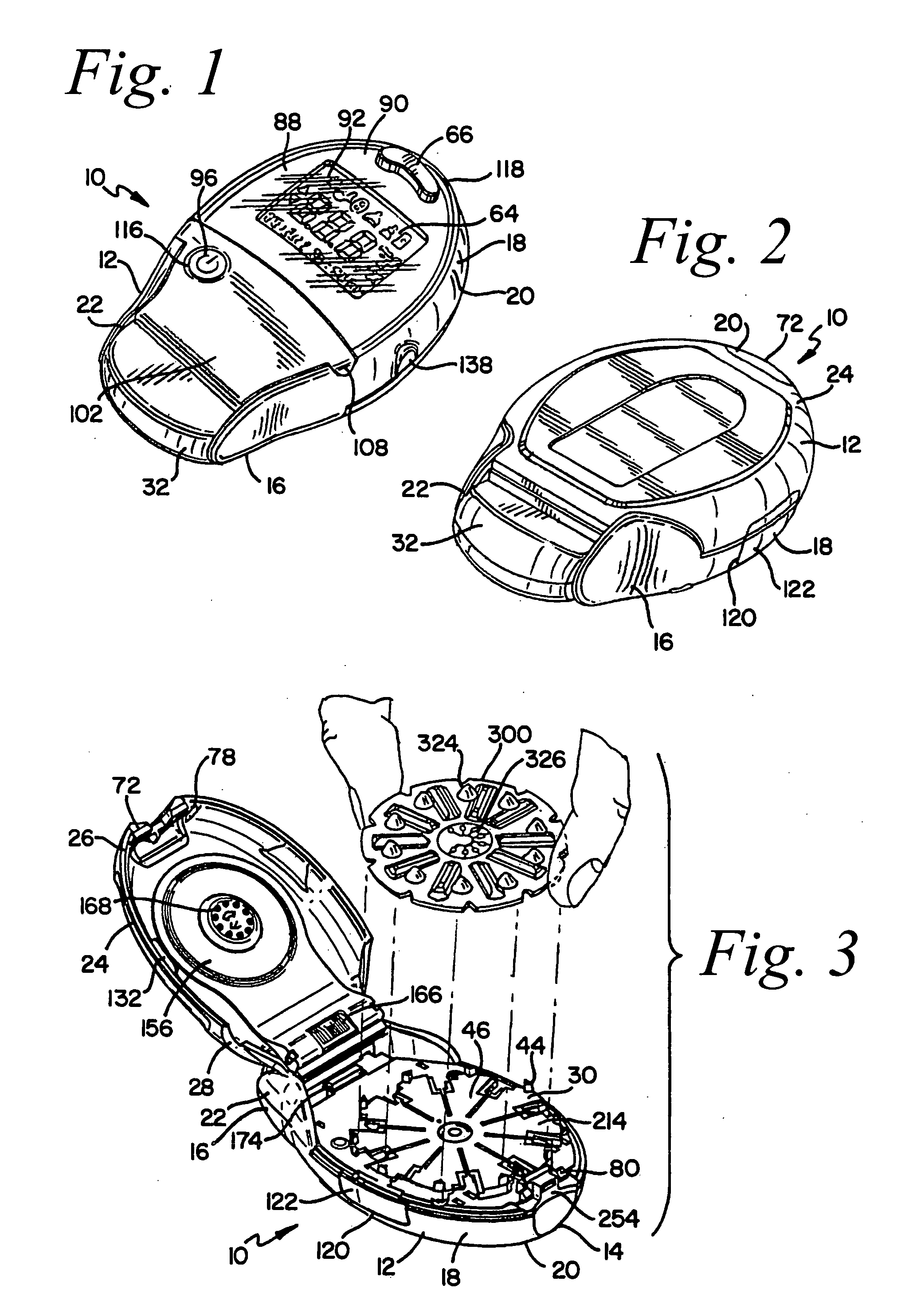
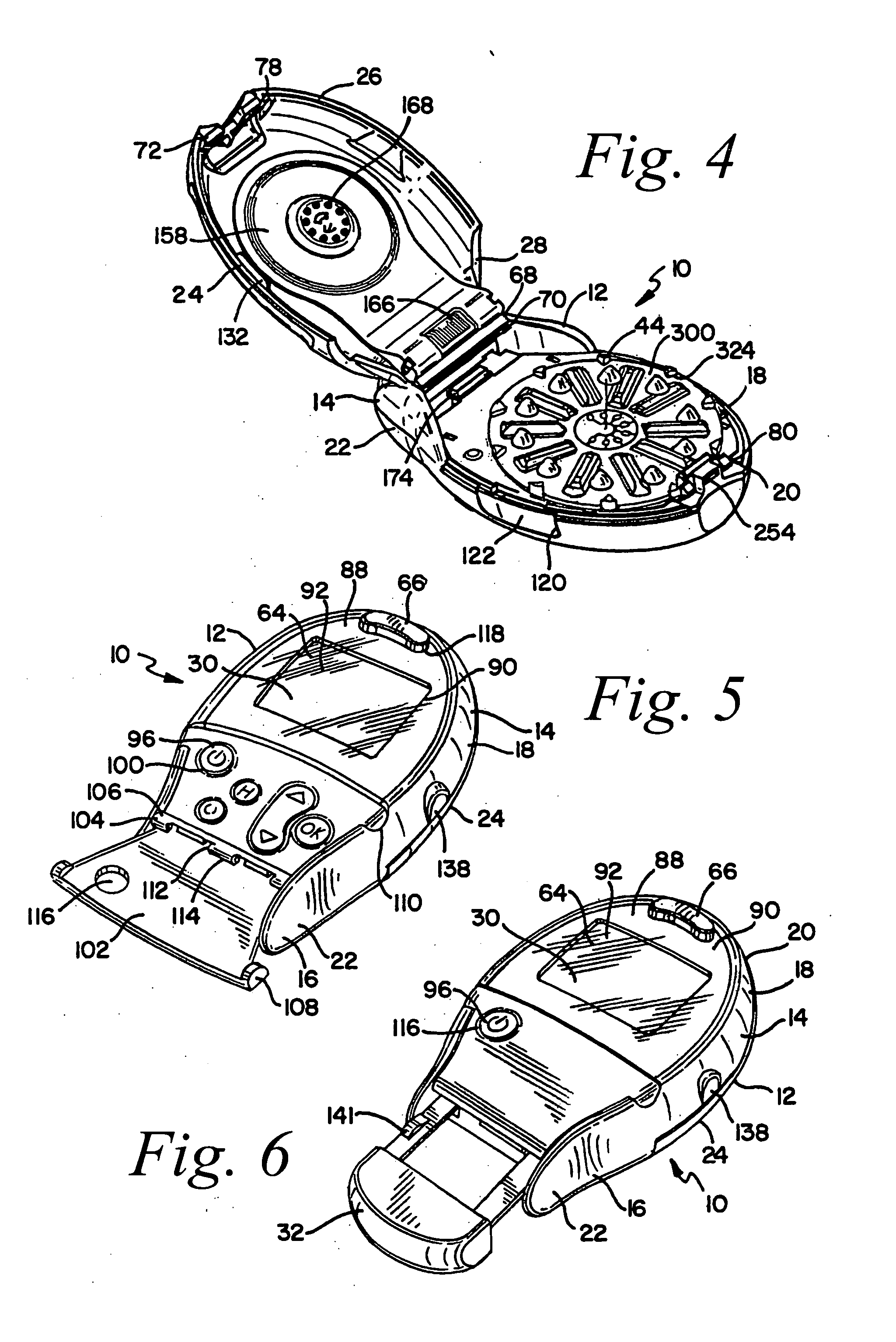
[0038] Referring now more specifically to the drawings, therein is disclosed a blood glucose sensor dispensing instrument generally designated by the reference numeral 10 and embodying the present invention. The sensor dispensing instrument 10 includes an outer housing 12 having an upper case 18 and a lower case 24, the lower case 24 pivoting on the upper case 18. The upper case 18 is pivotable with respect to the lower case 24 in a clamshell fashion so that a sensor pack 300 (see FIGS. 3 and 4) can be positioned on an indexing disk 30 within the housing 12. With the sensor pack 300 so loaded in the housing 12, a puller handle 32 extending from a rear end 22 of the upper case 18 of the housing 12 can be moved to activate a disk drive mechanism, generally designated by the numeral 34 (see FIG. 10), to load a sensor 302 into a testing position on the front end 14 of the housing 12 (see FIG. 3).

[0039] It should be noted that the sensor dispensing instrument 10 of the present invention...


PUM

PropertyMeasurementUnit
distanceaaaaaaaaaa
shapeaaaaaaaaaa
electricalaaaaaaaaaa

Abstract

A sensor dispensing instrument adapted to handle a sensor pack containing a plurality of sensors and to perform a test using one of the sensors. The sensor dispensing instrument includes an outer housing and a mechanical mechanism contained therein for rotating the sensor pack and ejecting one of the sensors from the sensor pack and through a sensor slot on the housing. The mechanical mechanism of the sensor dispensing instrument is operated by first moving a disk drive pusher in a first direction to rotate the sensor pack, and then moving the disk drive pusher in a second direction to eject a sensor from the sensor cavity and through the sensor slot.

Description

RELATED APPLICATIONS [0001] This application is a continuation of co-pending U.S. patent application Ser. No. 10 / 207,758, filed on Jul. 30, 2002 and is incorporated by reference in its entirety; U.S. patent application Ser. No. 10 / 207,758 claims the benefit of U.S. Provisional Patent Application Ser. No. 60 / 311,759, filed on Aug. 13, 2001, now expired.BACKGROUND OF THE INVENTION [0002] 1. Field of the Invention [0003] The present invention generally relates to a fluid monitoring system, and, more particularly, to a new and improved instrument for handling multiple sensors that are used in analyzing blood glucose or other analytes contained therein. [0004] 2. Description of the Prior Art [0005] People suffering from various forms of diabetes routinely need to test their blood to determine the level of blood glucose. The results of such tests can be used to determine what, if any, insulin or other medication needs to be administered. In one type of blood glucose testing system, sensor...

Claims


Application Information

Patent Timeline
Patent Type & Authority Applications(United States)
IPC IPC(8): G01N33/00G01N27/28B01L99/00G01N33/487G01N37/00G07F11/54
CPCG01N33/4875G07F11/54Y10T436/112499Y10T436/110833Y10T436/11
Inventor BROWN, MICHAEL K.MICINSKI, RUSSELL J.WHITSON, ROBERT C.
Owner BROWN MICHAEL K
Why Eureka
Try Eureka