Device for guiding an element in an orifice in a wall of a turbomachine combustion chamber

a technology of guiding device and combustion chamber, which is applied in the direction of mechanical equipment, machines/engines, light and heating equipment, etc., can solve the problems of affecting the guidance of the element by the device, and affecting the efficiency of the device. , to achieve the effect of simple, effective and economic

Active Publication Date: 2007-03-29
SN DETUDE & DE CONSTR DE MOTEURS DAVIATION S N E C M A
View PDF4 Cites 34 Cited by
  • Summary
  • Abstract
  • Description
  • Claims
  • Application Information

AI Technical Summary

Benefits of technology

[0007] The object of this invention in particular is to provi

Problems solved by technology

During operation of the turbomachine, the internal and external walls of the combustion chamber expand thermally and are subjected to considerable vibrations, which leads to relative displacements between the external wall of the chamber and the elements (igniters and starting injectors) which are mounted in orifices in this wall and which are supported by an external casing of the combustion chamber.
The ring and the bush delimit around the element a cylindrical annular passage

Method used


Image

  • Device for guiding an element in an orifice in a wall of a turbomachine combustion chamber
  • Device for guiding an element in an orifice in a wall of a turbomachine combustion chamber
  • Device for guiding an element in an orifice in a wall of a turbomachine combustion chamber

Examples


Embodiment Construction

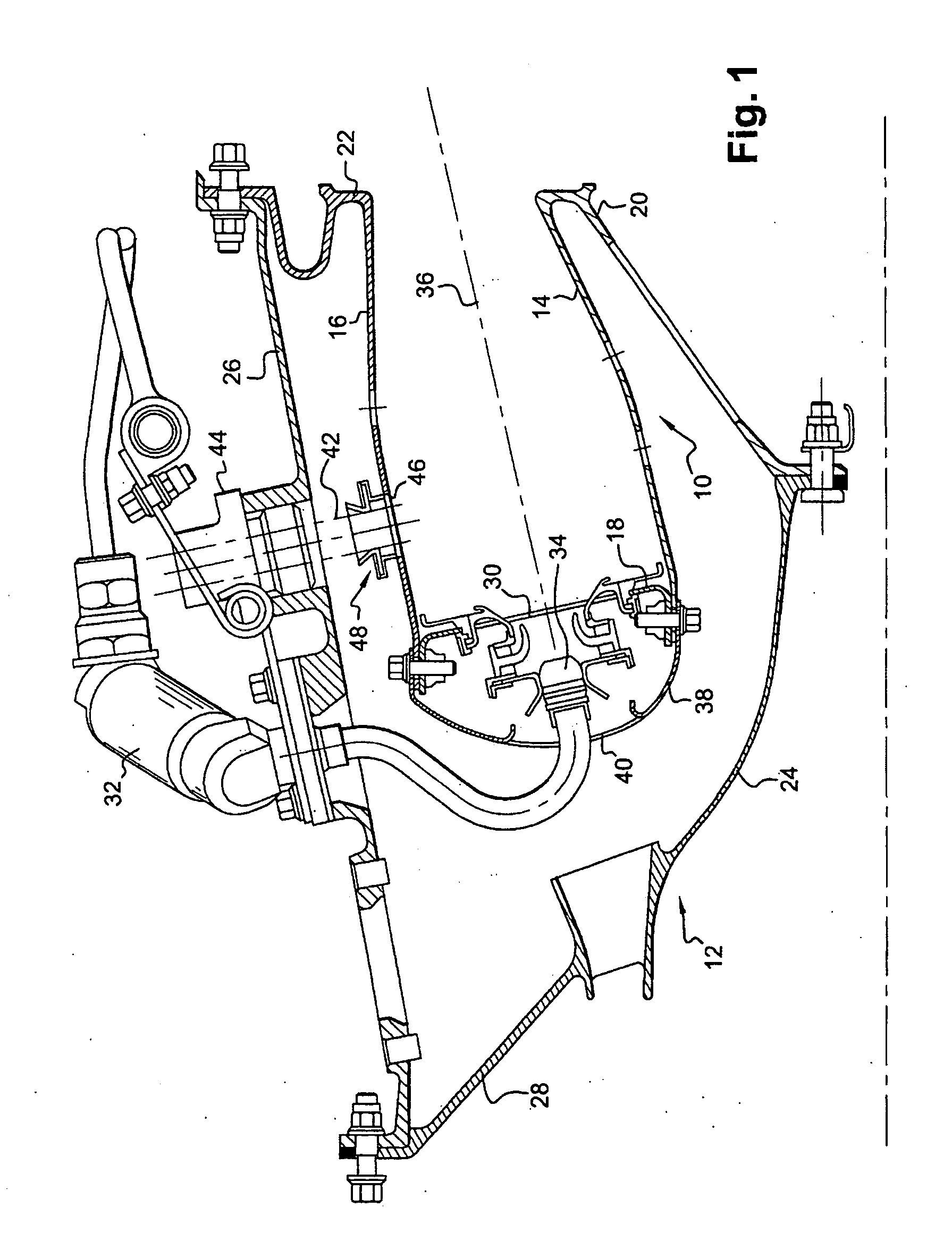
[0028] In FIG. 1, an annular combustion chamber 10 is arranged at the outlet of a diffuser 12, itself situated at the outlet of a compressor (not shown), and comprises an internal axisymmetric wall 14 and an external axisymmetric wall 16 which are connected upstream to an annular chamber endwall 18 and fastened downstream by respective internal 20 and external 22 annular flanges to an internal frustoconical shell 24 of the diffuser and to a downstream end of an external casing 26 of the chamber, the upstream end of this casing 26 being fastened to an external frustoconical shell 28 of the diffuser.

[0029] The chamber endwall 18 comprises orifices 30 through which air from the diffuser 12 and fuel fed in by injectors 32 pass, said injectors being fastened to the external casing 26 and being regularly distributed around a circumference about the longitudinal axis A of the chamber. Each injector 32 comprises a fuel injection head 34 mounted on the chamber endwall 18 and aligned with th...


PUM


Abstract

Device (48) for guiding an element in an orifice in a wall of a turbomachine combustion chamber (10), comprising a ring (50) and a bush (52), the ring being traversed axially by the element and comprising an external annular rim (60) guided transversely in an internal annular channel (52) of the bush, the ring and the bush delimiting around the element a cylindrical annular passage (76) opening into the chamber, air circulation means being formed in the ring and/or in the bush and distributed about their axis so as to establish an air circulation in the cylindrical passage from the outside of the combustion chamber toward the inside.

Description

BACKGROUND OF THE INVENTION AND DESCRIPTION OF THE PRIOR ART [0001] The present invention relates to a device for guiding an element, such as a spark igniter or a starting injector, extending in an orifice in a wall of a turbomachine combustion chamber. [0002] An annular turbomachine combustion chamber is delimited by coaxial axisymmetric walls which extend one inside the other and which are connected at their upstream ends by an annular chamber endwall comprising air supply orifices and fuel feed means. [0003] The external wall of the chamber comprises, in the vicinity of its upstream end, at least one passage orifice for a spark igniter intended to initiate the combustion of the fuel / air mixture in the chamber. In certain cases, starting injectors, independent of the aforementioned fuel feed means, are likewise mounted in orifices in the external wall and distributed about the axis of the chamber, in order to improve initiation of the combustion of the air / fuel mixture in the cham...

Claims


Application Information

Patent Timeline
IPC IPC(8): F23R3/02
CPCF02C3/14F23R3/002F23R2900/00012F23R3/50F23R3/60F23R3/283
Inventor GAUTIER, CLAUDESANDELIS, DENIS JEAN MAURICE
Owner SN DETUDE & DE CONSTR DE MOTEURS DAVIATION S N E C M A
Why Eureka
Try Eureka