Turbomachine exhaust case drain
a turbomachine and exhaust case technology, applied in the direction of machines/engines, stators, liquid fuel engines, etc., can solve the problems of inability to easily control, long and difficult operation, and inability to stabilize liquids, so as to simplify the mounting operation, reduce work time, and improve efficiency
- Summary
- Abstract
- Description
- Claims
- Application Information
AI Technical Summary
Benefits of technology
Problems solved by technology
Method used
Image
Examples
Embodiment Construction
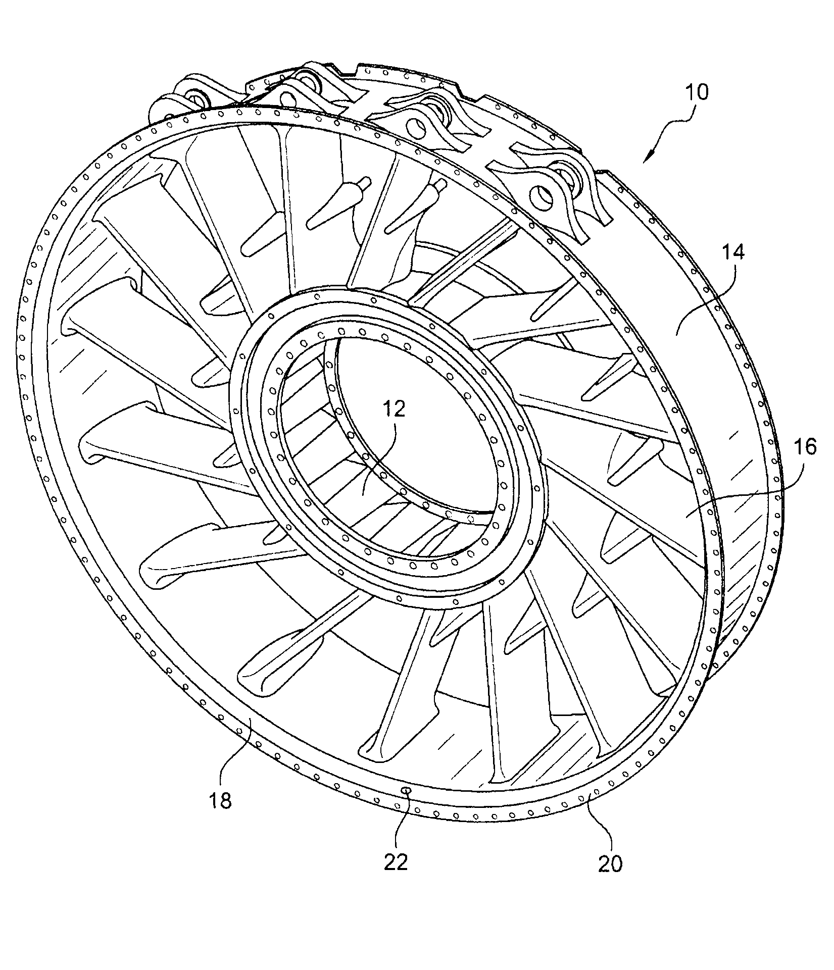
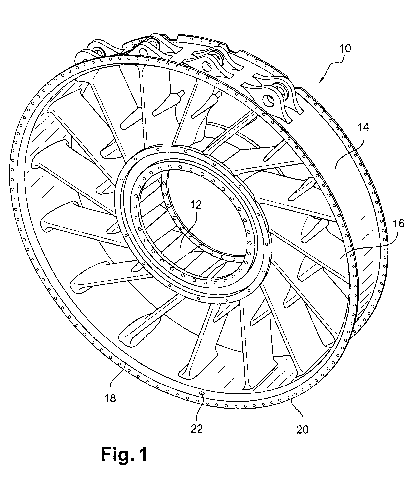
[0025]Reference will be made first of all to FIG. 1, which shows a turbomachine exhaust case 10 of a known type, as seen from the upstream end, comprising two coaxial cylindrical shells, one inner shell 12 and one outer shell 14, connected by oblique arms 16. The outer shell 14 includes at its upstream end an annular groove 18 which is situated downstream and in the vicinity of the upstream mounting flange 20 of the exhaust case, a region of which groove situated “at 6 o'clock”, that is to say at the bottom, is perforated with a discharge orifice 22 provided with a drain intended to outwardly discharge liquids liable to be collected in this groove.
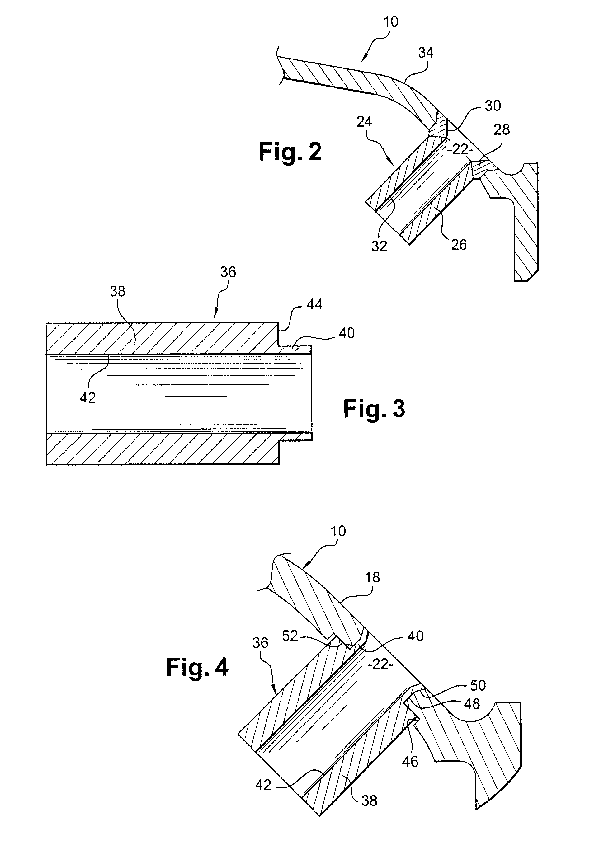
[0026]FIG. 2 is a larger-scale view of the discharge orifice 22 and its drain 24, which is formed by a tubular cylindrical body 26 fastened to the rim of the orifice 22 by an annular weld 28 formed around the periphery of this orifice. The surface 30 of the weld 28 that connects the internal wall 32 of the drain to the internal wall 34 of ...
PUM
 Abstract
Description
Claims
Application Information
 - R&D
- Intellectual Property
- Life Sciences
- Materials
- Tech Scout
- Unparalleled Data Quality
- Higher Quality Content
- 60% Fewer Hallucinations
Browse by: Latest US Patents, China's latest patents, Technical Efficacy Thesaurus, Application Domain, Technology Topic, Popular Technical Reports.
© 2025 PatSnap. All rights reserved.Legal|Privacy policy|Modern Slavery Act Transparency Statement|Sitemap|About US| Contact US: help@patsnap.com


