
System for injecting a mixture of air and fuel into a turbomachine combustion chamber
a technology of air and fuel mixture and combustion chamber, which is applied in the direction of combustion process, hot gas positive displacement engine plant, lighting and heating apparatus, etc., can solve the problems of shortening the life of the venturi and increasing the production of harmful gases discharged into the atmosphere, and achieves the effect of simple, effective and economic
- Summary
- Abstract
- Description
- Claims
- Application Information
AI Technical Summary
Benefits of technology
Problems solved by technology
Method used
Image

Examples
Embodiment Construction
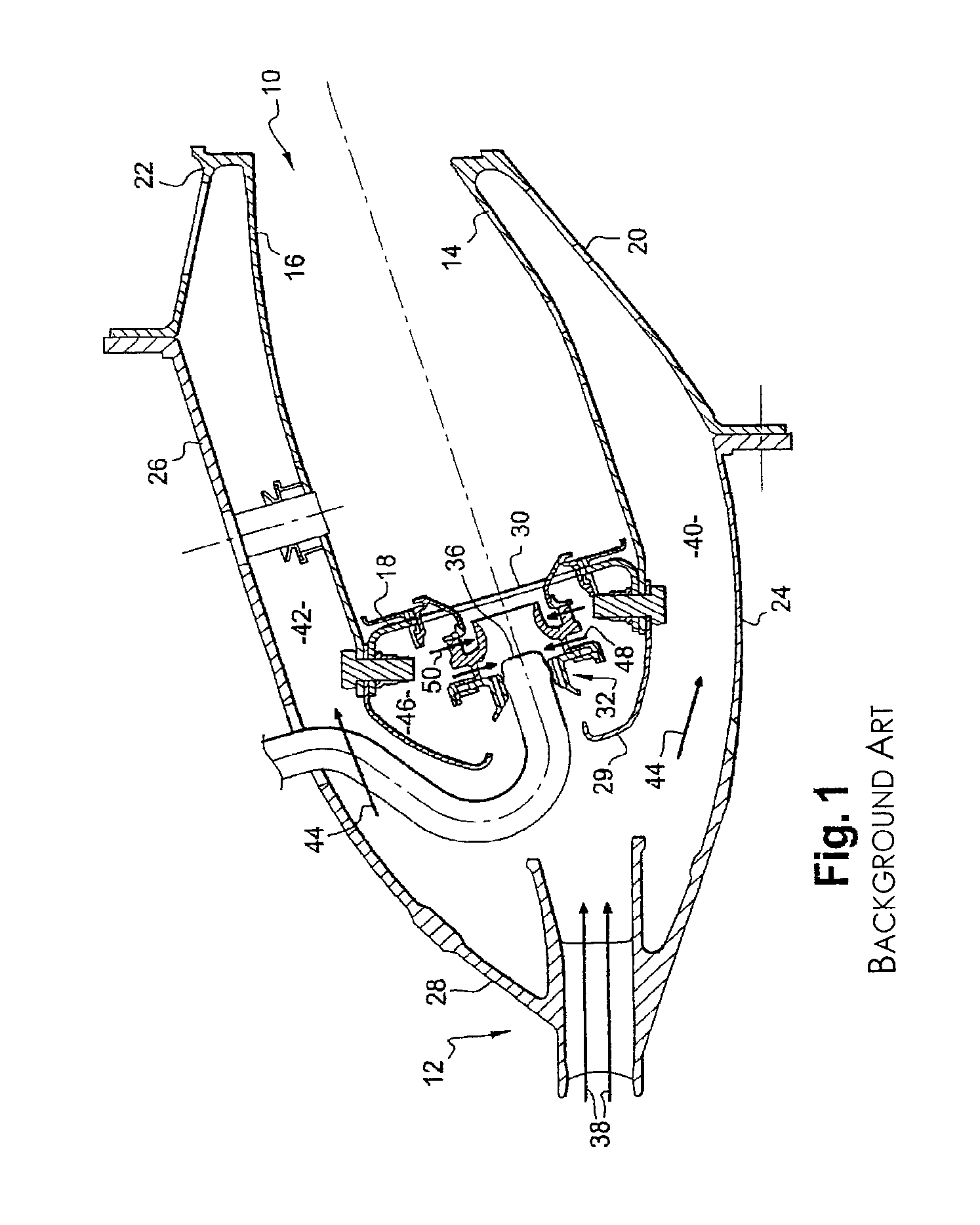
[0031]FIG. 1 depicts an annular combustion chamber 10 of a turbomachine such as an aircraft turbojet or turboprop engine, this chamber being positioned at the outlet of a diffuser 12 itself situated at the outlet of a compressor (not depicted). The chamber 10 has an internal axisymmetric wall 14 and an external axisymmetric wall 16 which are connected at the upstream end to an annular chamber end wall 18 and fixed at the downstream end by respective internal 20 and external 22 frustoconical shell rings to an internal frustoconical partition wall 24 of the diffuser and to an external casing 26 of the chamber, respectively, the upstream end of this casing 26 being connected to an external frustoconical partition wall 28 of the diffuser.
[0032]An annular cowling 29 is fixed to the upstream ends of the walls 14, 16 and 18 of the chamber and has air passage orifices aligned with openings 30 in the chamber end wall 18, in which openings systems 32 for injecting a mixture of air and of fuel...
PUM
 Abstract
Description
Claims
Application Information