
Method of calibrating the mass of components intended to be mounted at the periphery of a rotor

Active Publication Date: 2006-12-07
SN DETUDE & DE CONSTR DE MOTEURS DAVIATION S N E C M A
View PDF9 Cites 8 Cited by
  • Summary
  • Abstract
  • Description
  • Claims
  • Application Information

AI Technical Summary

Benefits of technology

[0008] The particular subject of the invention is to prevent all of these disadvantages and to provide a simple, effective and economic solution to calibrating the mass of components of this type.
[0011] The removal of material in a region situated on one of the axes of inertia of the component makes it possible to preserve the static balancing of the component about this axis and therefore prevent it from tilting about this axis during operation.
[0012] The invention has many advantages. It avoids the use of weights, which increases the mass of the components, and therefore the mass of the turbomachine, and reduces the engine performance, this use of weights also being very expensive compared with the machining operation of the method according to the invention. It also avoids the procurement and storage of weights and adhesive.

Problems solved by technology

The addition of one or more weights modifies the position of the center of gravity of the platform, which may cause the platform to tilt during operation about the points where it is fastened to the rotor, resulting in separations of the air stream with a deterioration in the engine performance.

Method used


Image

  • Method of calibrating the mass of components intended to be mounted at the periphery of a rotor
  • Method of calibrating the mass of components intended to be mounted at the periphery of a rotor
  • Method of calibrating the mass of components intended to be mounted at the periphery of a rotor

Examples


Embodiment Construction

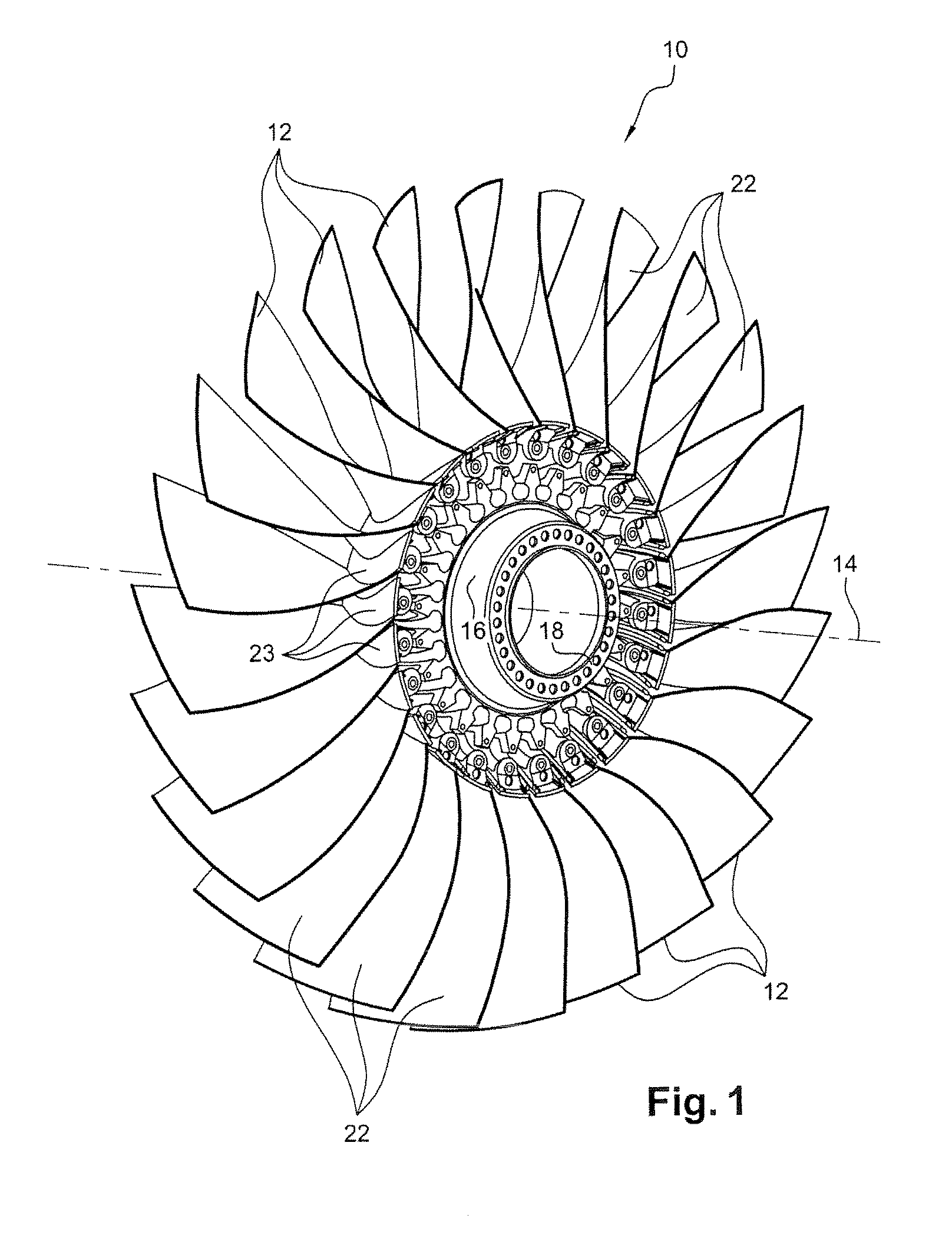
[0025]FIG. 1 depicts a fan rotor 10 of a turbomachine such as a turbojet or a turboprop, comprising a plurality of blades 12 which extend radially around the axis 14 of the fan and are borne by a disk 16.

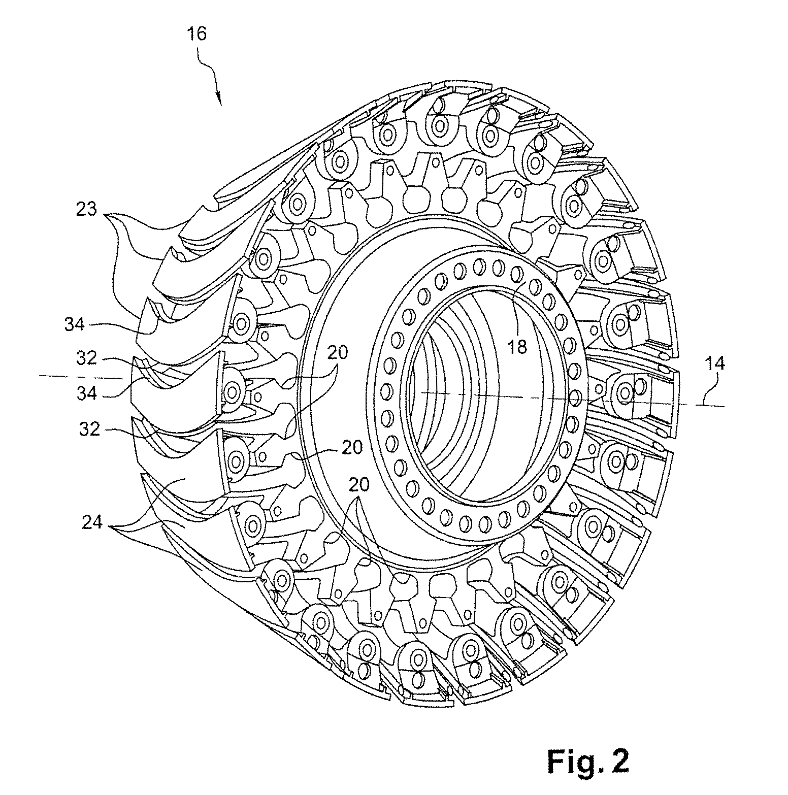
[0026] The disk 16 comprises a downstream annular flange 18 for fastening to a shaft of the turbomachine.

[0027] At their radially internal end, the blades 12 each have a root (not shown) which is fitted into a corresponding groove 20 provided in the external periphery of the disk 16 (FIG. 2).

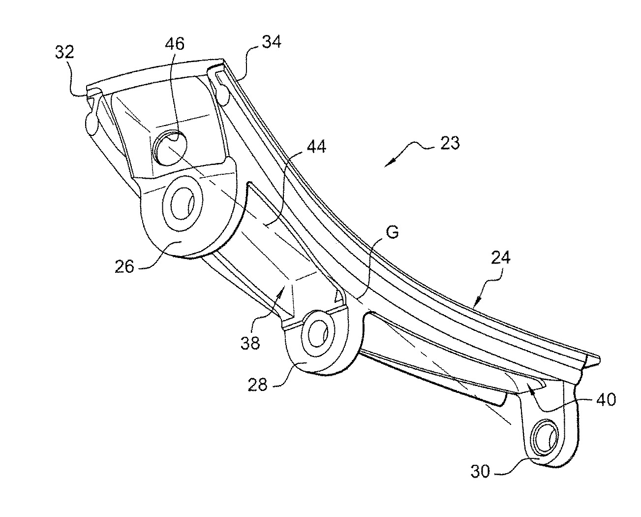
[0028] During operation of the turbomachine, the path of the air flow circulating between the twisted airfoils 22 of the blades is delimited externally by the internal wall of a casing and internally by platforms 23 extending between the roots of the fan blades 12.

[0029] Each platform 23 comprises a wall 24 which delimits internally the path of the air flow between two adjacent blades, and fastening flanges 26, 28 and 30, numbering three in this case, which extend substantially toward the ax...


PUM


Abstract

Method of calibrating the mass of components intended to be mounted at the periphery of a rotor A method of calibrating the mass of components intended to be mounted at the periphery of a rotor, the method consisting, for each of the components, in removing by machining a volume of material in a region of the component situated on one of its axes of inertia in order to bring the mass of the component to a predetermined value.

Description

BACKGROUND OF THE INVENTION AND DESCRIPTION OF THE PRIOR ART [0001] The present invention relates to a method of calibrating the mass of identical and interchangeable components intended to be mounted at the periphery of a rotor, in particular of a fan in a turbomachine such as a turbojet or a turboprop. [0002] The air flow path is delimited internally at the inlet of the fan by elongate platforms which are arranged between the roots of the fan blades and fastened to the rotor of the fan. [0003] These platforms are identical and interchangeable components which must have the same mass, with a low tolerance which may be less than a gram, for example. [0004] The manufacture of these platforms generates a relatively wide spread in the mass, thus making it necessary to calibrate the mass to compensate for this spread. [0005] In practice, one solution consists in weighing each platform and in adhesively bonding at least one resin weight or elastomer weight in a longitudinal cavity in the...

Claims


Application Information

Patent Timeline
IPC IPC(8): G01M1/34
CPCG01M1/34F01D5/027F01D11/008Y02T50/60
Inventor AUDIC, STEPHANELEFEBVRE, ERIC JACQUESNITRE, THIERRY
Owner SN DETUDE & DE CONSTR DE MOTEURS DAVIATION S N E C M A
Learn More