Stage of variable-pitch vanes for a turbomachine

a turbomachine and variable pitch technology, applied in the field of turbomachines, can solve the problems of unwanted rotational movements of pins about their axes, wear on the rib of the shroud, and the replacement of the annular shroud, etc., and achieve the effect of simple, effective and economi

Active Publication Date: 2009-04-02
SN DETUDE & DE CONSTR DE MOTEURS DAVIATION S N E C M A
View PDF7 Cites 7 Cited by
  • Summary
  • Abstract
  • Description
  • Claims
  • Application Information

AI Technical Summary

Benefits of technology

[0007]A particular object of the invention is to provide a simple, effective and economic solution to this problem.

Problems solved by technology

In operation, during the rotation of a variable-pitch vane about its axis, the internal pivot of this vane is caused to rub against the cylindrical pins situated on either side of this pivot, thus resulting in unwanted rotational movements of the pins about their axes.
These unwanted movements combine with the vibrations of the engine and cause wear on the rib of the shroud as a result of the bottoms of the notches in the cylindrical pins rubbing and bearing against this rib.
When the degree of wear on this rib has exceeded a certain threshold, it is required to replace the annular shroud, which is a long and costly operation.

Method used


Image

  • Stage of variable-pitch vanes for a turbomachine
  • Stage of variable-pitch vanes for a turbomachine
  • Stage of variable-pitch vanes for a turbomachine

Examples


Embodiment Construction

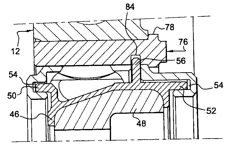
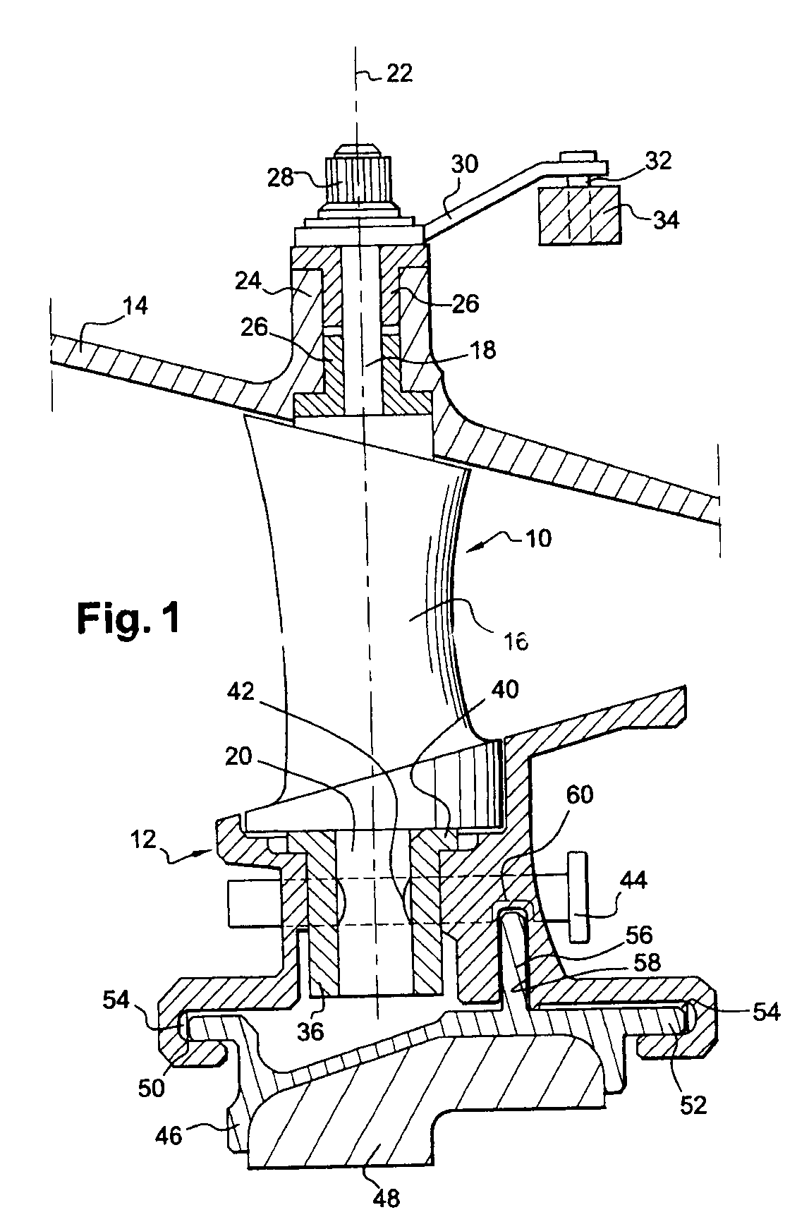
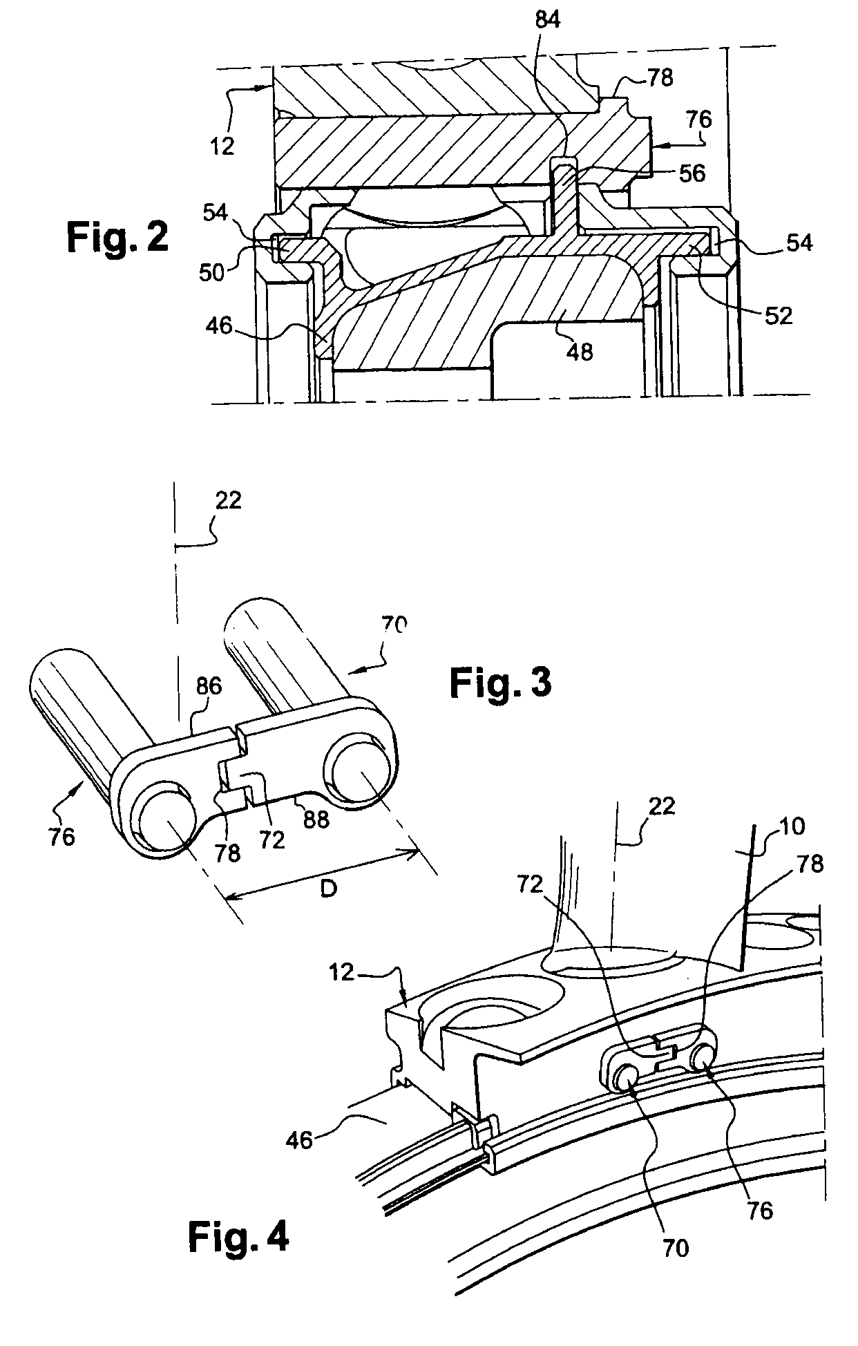
[0020]FIG. 1 shows a stage of variable-pitch vanes 10 of a high-pressure compressor of a turbomachine, these vanes 10 being uniformly distributed around the axis of the turbomachine and extending between a sectorized internal ring 12 and an external casing 14 of the turbomachine.

[0021]Each vane 10 comprises an airfoil 16 connected at each of its radially internal and external ends to a radial cylindrical pivot 18, 20 which extends along the axis 22 of rotation of the vane.

[0022]The external cylindrical pivot 18, or actuating pivot, is engaged in a cylindrical duct 24 of the casing and is centered and rotationally guided in this duct by two identical cylindrical bushes 26 mounted in a mutually inverted arrangement around the external pivot 18.

[0023]The radially external end of the external pivot 18 is threaded and fastened by means of a nut 28 to one end of an actuating lever 30. The other end of the actuating lever 30 carries a finger 32 which is crimped onto this end of the lever a...


PUM


Abstract

A stage of variable-pitch vanes for a turbomachine, these vanes (10) comprising internal pivots engaged in corresponding housings of a sectorized internal ring (12), each ring sector comprising axial orifices for mounting two pins (70, 76) for the radial retention of the ring sector on the internal pivot of a vane, wherein each pin (70, 76) comprises means (72, 78) cooperating by shape coupling with complementary means (78, 72) of the other pin (76, 70) in order to rotationally immobilize these pins in the orifices in the ring sectors.

Description

[0001]The present invention relates to a stage of variable-pitch vanes for a turbomachine such as an aircraft turbojet or turboprop.BACKGROUND OF THE INVENTION[0002]In a turbomachine, stages of variable-pitch vanes are mounted between rotor disks of a high-pressure compressor. These variable-pitch vanes are carried by the stator and can be adjusted in position about their axes in order to optimize the flow of gases into the engine of the turbomachine.[0003]A variable-pitch vane comprises an axial cylindrical pivot at each of its ends, these pivots defining the axis of rotation of the vane. The radially external pivot, termed actuating pivot, is engaged in a cylindrical duct of a casing of the turbomachine and is connected by a connecting rod to an actuating ring operated by a ram or an electric motor. The rotation of the actuating ring is transmitted by the connecting rods to the external pivots of the vanes and causes them to turn about their axes.[0004]The radially internal pivot,...

Claims


Application Information

Patent Timeline
Patent Type & Authority Applications(United States)
IPC IPC(8): F01D17/12F01D9/04
CPCF01D5/3023F01D5/3053F16B19/02F01D17/162F04D29/563F01D11/001
Inventor LEJARS, CLAUDE ROBERT LOUISSTAESSEN, RICHARD
Owner SN DETUDE & DE CONSTR DE MOTEURS DAVIATION S N E C M A
Why Eureka
Try Eureka