
Under travel actuator, particularly for automobile clutch

a technology of actuator and travel plate, which is applied in the direction of mechanical actuator clutch, mechanical apparatus, gearing, etc., can solve the problems of displacement of pressure plate and thereby driving mechanism, and the known solutions are all relatively complex

Active Publication Date: 2012-07-17
VALEO EMBRAYAGES SAS
View PDF10 Cites 3 Cited by
  • Summary
  • Abstract
  • Description
  • Claims
  • Application Information

AI Technical Summary

Benefits of technology

[0011]The aim of the present invention is, in particular, to respond to this need in a simple, effective and economic manner.
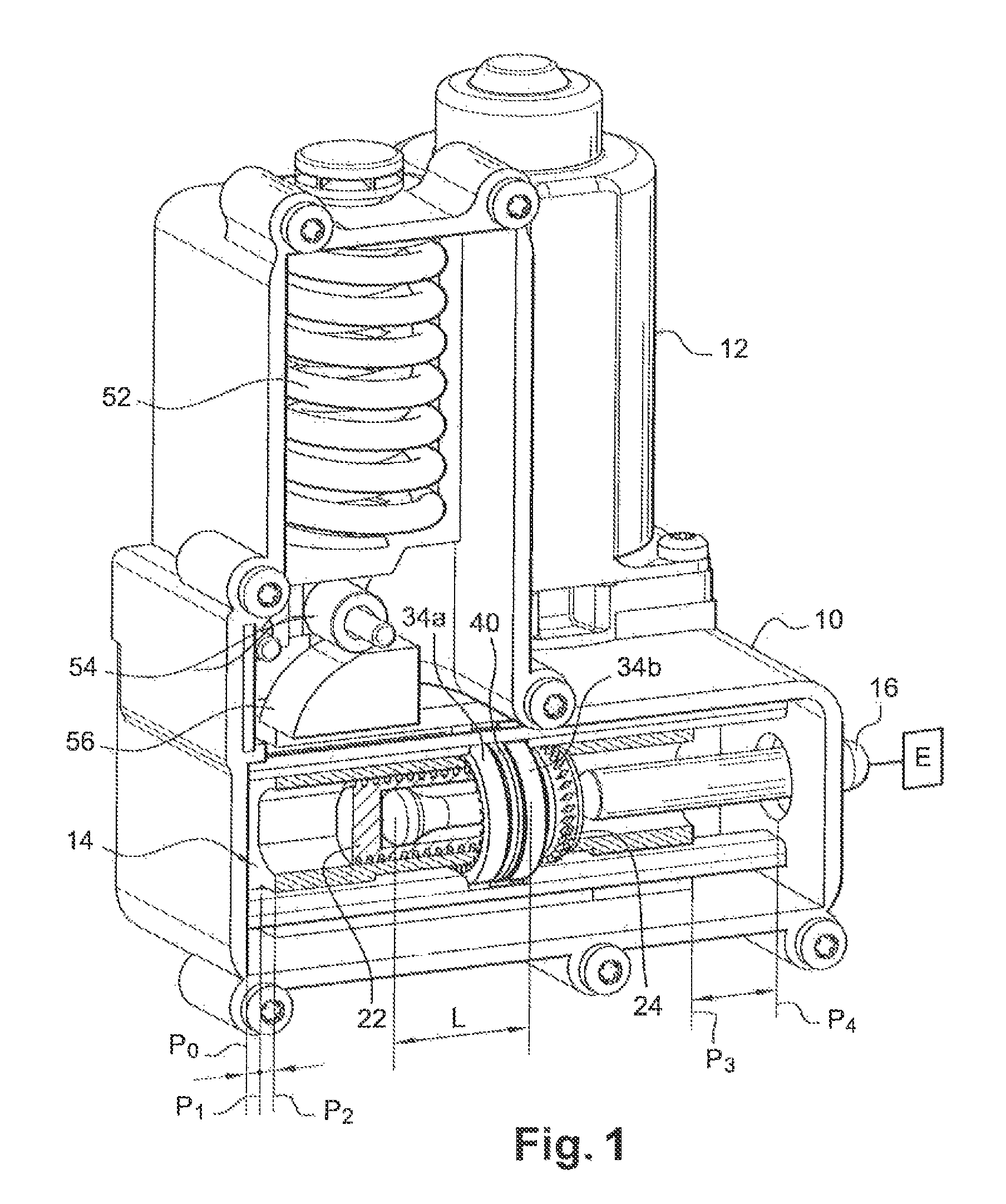
[0016]In this way, according to the present invention, the means of travel compensation, especially in cases where worn friction linings of a clutch have to be compensated, are incorporated in the actuator and not in the clutch mechanism itself, and are thus exposed to much lower stress levels, thereby improving their operating reliability and precision.

Problems solved by technology

When the friction linings of the clutch start to show signs of wear, the pressure plate and thereby also the driving mechanism become displaced as a result of the modification to the travel of this element and by changes in the amount of effort needed to operate its respective actions.
However, these known solutions are all relatively complex and in practice their precision and their reliability have frequently been found wanting.

Method used


Image

  • Under travel actuator, particularly for automobile clutch
  • Under travel actuator, particularly for automobile clutch
  • Under travel actuator, particularly for automobile clutch

Examples


Embodiment Construction

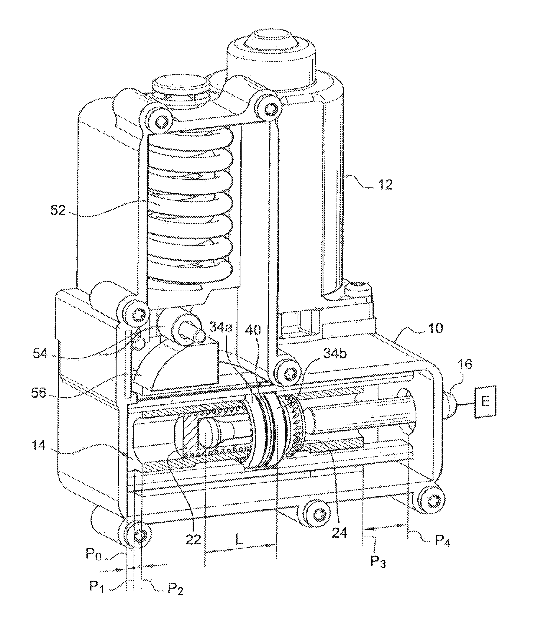
[0033]The actuator shown in FIG. 1 is intended to be used for the operation of the clutch of a motor vehicle and comprises essentially a casing 10 on which is mounted an electric motor 12, the output shaft of which is connected by a reducing system and a rack (not shown) to a mobile element 14 that is guided and moved inside the casing 10 in a manner perpendicular to the axis of the electric motor 12, with the said mobile element acting through the intermediary of a pusher member 16 on a clutch system E, for example, on a clutch pressure plate.

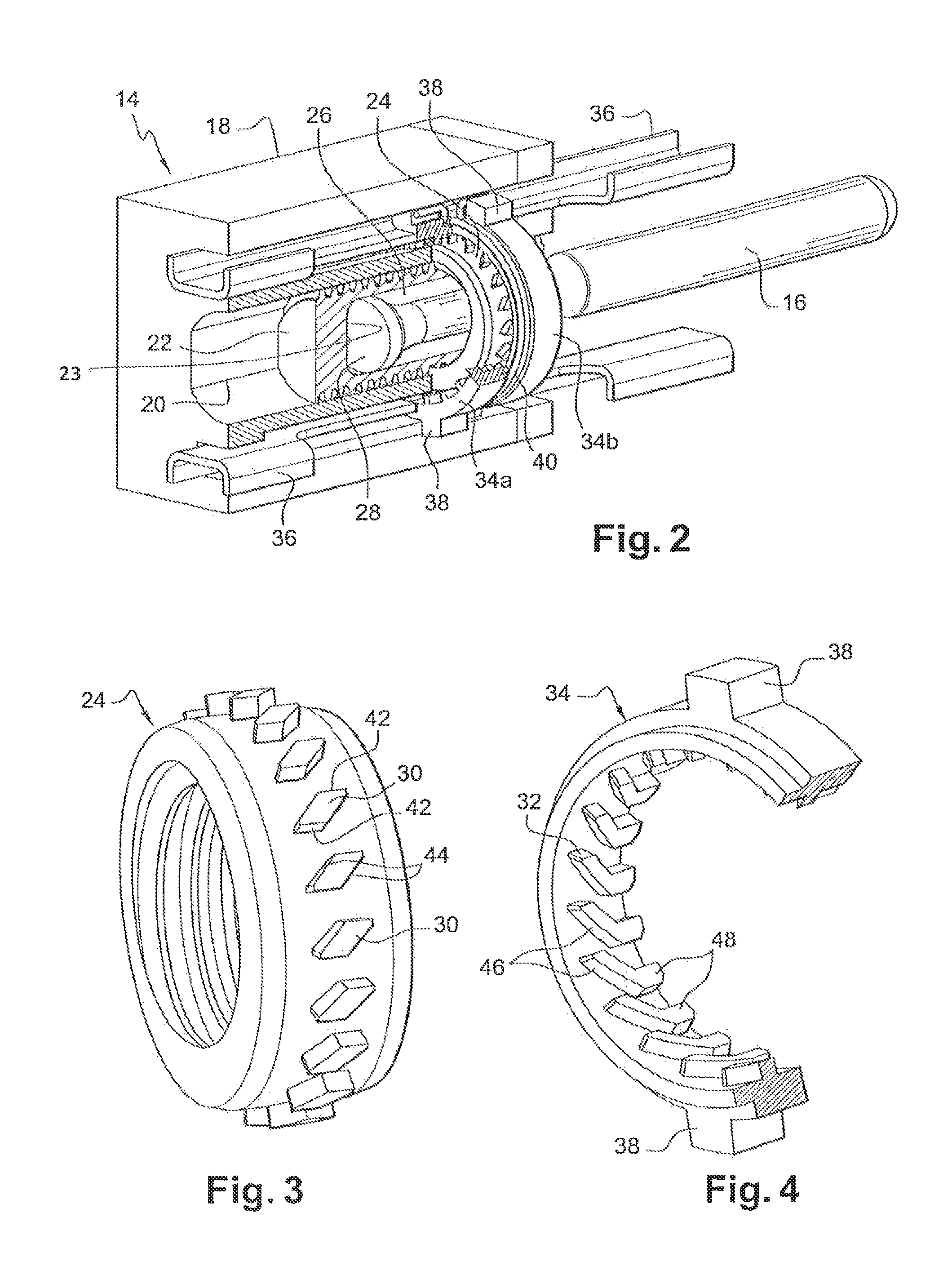
[0034]The mobile element 14, which is better seen in FIG. 2, comprises essentially a slide element 18 activated by the electric motor 12 and is connected to the pusher member 16 by travel compensation means, which enables the axial displacement of the pusher member 16 caused by the wear sustained by the friction linings of the clutch to be compensated.

[0035]For this purpose, the slide element 18 has an axial passage 20 in which a screw 22 is m...


PUM


Abstract

An under travel actuator, particularly intended for an automobile clutch, including an engine (12) for the translation movement of a mobile gear (14) acting on a push stem (16) for the opening and closing of the clutch, the mobile gear including screw-nut means (22, 24) cooperating with two combined means of unidirectional driving in order to regulate the length of the push stem (16) according to the wear of the clutch surfaces subject to friction.

Description

CROSS-REFERENCE TO RELATED APPLICATIONS AND CLAIM TO PRIORITY[0001]This application relates to International Application No. PCT / FR2007 / 051311 filed May 22, 2007 and French Patent Application No. 0651935 filed May 29, 2006, of which the disclosures are incorporated herein by reference and to which priority is claimed.BACKGROUND OF THE INVENTION[0002]1. Field of the Invention[0003]The invention concerns a travel compensation actuator, in particular for a motor vehicle clutch.[0004]2. Description of Related Art[0005]An actuator of this type comprises an electrical reduction motor, which operates a driving mechanism, such as for example, a pusher member acting directly or otherwise on the system to be operated, for example, a clutch pressure plate.[0006]If the actuator is of the effort compensating type, it will generally comprise a compensating spring, which acts on a cam or an inclined ramp that is connected to the said driving mechanism so as to apply a force to this mechanism in a ...

Claims


Application Information

Patent Timeline
IPC IPC(8): F16H1/20
CPCF16D13/752F16D28/00Y10T74/18608Y10T74/1527Y10T74/18576F16D27/00F16D13/75
Inventor MAUREL, HERVE
Owner VALEO EMBRAYAGES SAS
Learn More