System for ventilating a downstream cavity of an impellor of a centrifugal compressor

a centrifugal compressor and downstream cavity technology, which is applied in the direction of machines/engines, combination engines, liquid fuel engines, etc., can solve the problems of reducing the performance of turbomachines, increasing weight and inertia, etc., and achieves the effect of simple, effective and economic

Active Publication Date: 2010-02-04
SN DETUDE & DE CONSTR DE MOTEURS DAVIATION S N E C M A
View PDF2 Cites 8 Cited by
  • Summary
  • Abstract
  • Description
  • Claims
  • Application Information

AI Technical Summary

Benefits of technology

[0005]The object of the invention is in particular to provide a simple, effective and economic solution to these problems.

Problems solved by technology

However, the attachment of this shield to the impellor is complex and causes an increase in the weight and inertia in rotation of the compressor impellor, which can reduce the performance of the turbomachine.

Method used


Image

  • System for ventilating a downstream cavity of an impellor of a centrifugal compressor
  • System for ventilating a downstream cavity of an impellor of a centrifugal compressor
  • System for ventilating a downstream cavity of an impellor of a centrifugal compressor

Examples


Embodiment Construction

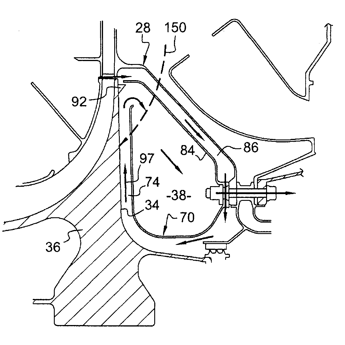
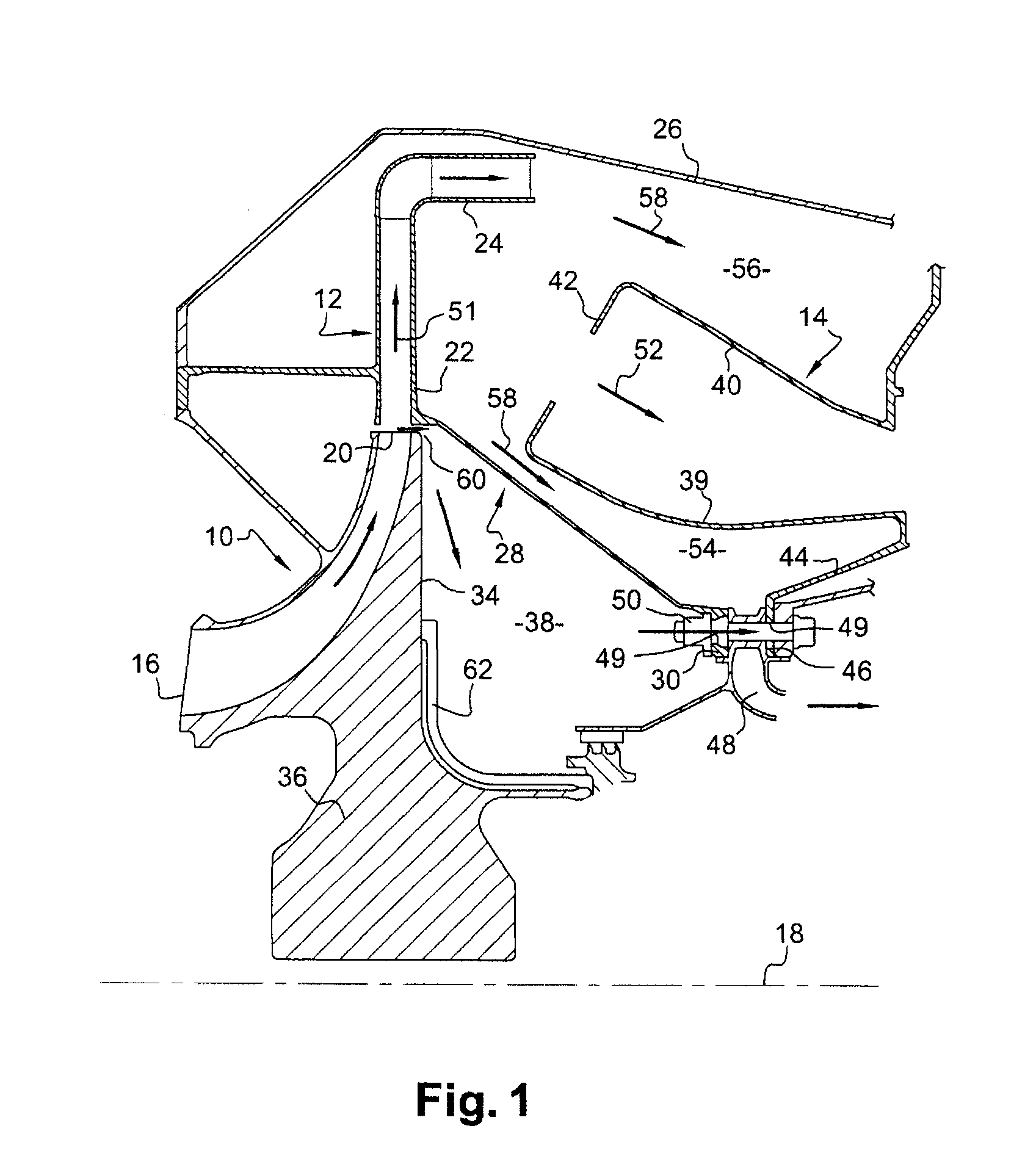
[0020]Reference is made first of all to FIG. 1 which represents a portion of a turbomachine, such as an aircraft turbojet or turboprop, comprising, from upstream to downstream, in the direction of flow of the gases inside the turbomachine, a compressor centrifugal stage 10, an annular diffuser 12 and a combustion chamber 14.

[0021]The inlet 16 of the centrifugal stage 10 is oriented upstream, substantially parallel to the axis 18 of the turbomachine, and its outlet 20 is oriented outward, substantially perpendicularly to the axis 18, and is aligned with a radial inlet 22 of the diffuser 12. This diffuser is of annular shape bent substantially at 900 and comprises an annular outlet 24 that is oriented parallel to the axis of the turbomachine and that emerges into an annular enclosure in which the combustion chamber 14 is mounted.

[0022]The diffuser 12 is supported by an external casing 26 of the turbomachine that externally surrounds the compressor 10, the diffuser 12 and the combustio...


PUM


Abstract

A system for ventilating a downstream cavity of an impellor of a centrifugal compressor in a turbomachine, this system comprising flow diversion means (70, 84) mounted fixedly in the downstream cavity (38) of the impellor (36) in order to divert the ventilation air taken from the outlet of the compressor (10) and cause it to circulate radially from the inside to the outside along the downstream face (34) of the impellor.

Description

[0001]The present invention relates to a system for ventilating a downstream cavity of an impellor of a centrifugal compressor in a turbomachine such as in particular an aircraft turbojet or turboprop or a gas generator.BACKGROUND OF THE INVENTION[0002]The annular cavity that is formed downstream of the rotor or impellor of a centrifugal compressor in a turbomachine must be ventilated to take away the heat energy generated by the impellor. This ventilation is usually provided by taking air from the output of the compressor, at the junction with the inlet of an annular diffuser that supplies a combustion chamber.[0003]This ventilation air that already has a relatively high temperature, heats up through viscous friction on the downstream face of the impellor while running from the outside to the inside in the downstream cavity of the impellor, the air becoming hotter as it comes closer to the axis of rotation of the impellor. This hot air may, by convection, raise the temperature of t...

Claims


Application Information

Patent Timeline
Patent Type & Authority Applications(United States)
IPC IPC(8): F04D29/00
CPCF01D11/04F01D25/12F02C7/18Y02T50/675F04D29/584Y02T50/671F04D29/284Y02T50/60
Inventor ARGAUD, THIERRYBRUNET, ANTOINE ROBERT ALAINLEININGER, JEAN-CHRISTOPHE
Owner SN DETUDE & DE CONSTR DE MOTEURS DAVIATION S N E C M A
Why Eureka
Try Eureka