
Light pad charger for electronic devices

a charger and electronic device technology, applied in the direction of electrochemical generators, secondary cell servicing/maintenance, transportation and packaging, etc., can solve the problems of reducing the overall efficiency, not only coupleing, and time-consuming and sometimes tedious plugging into the device specific connector

Inactive Publication Date: 2007-03-29
GOOGLE TECH HLDG LLC
View PDF0 Cites 61 Cited by
  • Summary
  • Abstract
  • Description
  • Claims
  • Application Information

AI Technical Summary

Benefits of technology

[0059] Accordingly, the specification and figures are to be regarded in an illustrative rather than a restrictive sense, and all such modifications are intended to be included within the scope of present invention. The benefits, advantages, solutions to problems, and any element(s) that may cause any benefit, advantage, or solution to occur or become more pronounced are not to be construed as a critical, required, or essential features or elements of any or all the claims. The invention is defined solely by the appended claims including any amendments made during the pendency of this application and all equivalents of those claims as issued.

Problems solved by technology

The problem with this traditional method is that some users, in today's hustle and bustle world, find that plugging the device specific connector into the device is time consuming and sometimes tedious.
The problem with these inductive chargers is twofold: First, the primary and secondary must be precisely aligned for maximum coupling, and thus maximum charging efficiency.
A slight misalignment can greatly reduce the overall efficiency.
Second, the electromagnetic field is generally emitted uniformly, causing it to not only couple to the secondary, but to other objects as well.
This stray coupling can compromise the energy transfer.
This energy is wasted.

Method used


Image

  • Light pad charger for electronic devices
  • Light pad charger for electronic devices
  • Light pad charger for electronic devices

Examples


Embodiment Construction

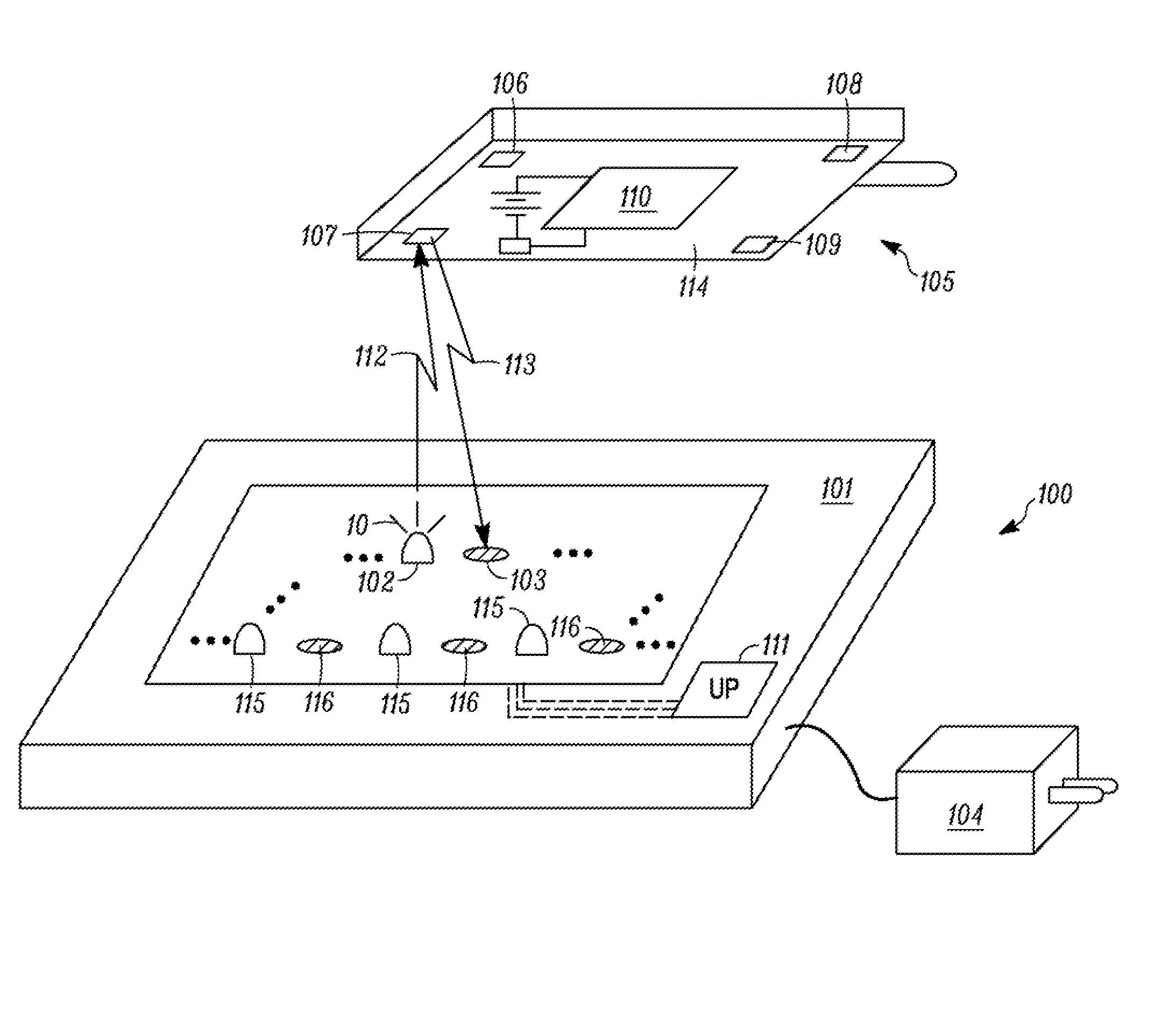
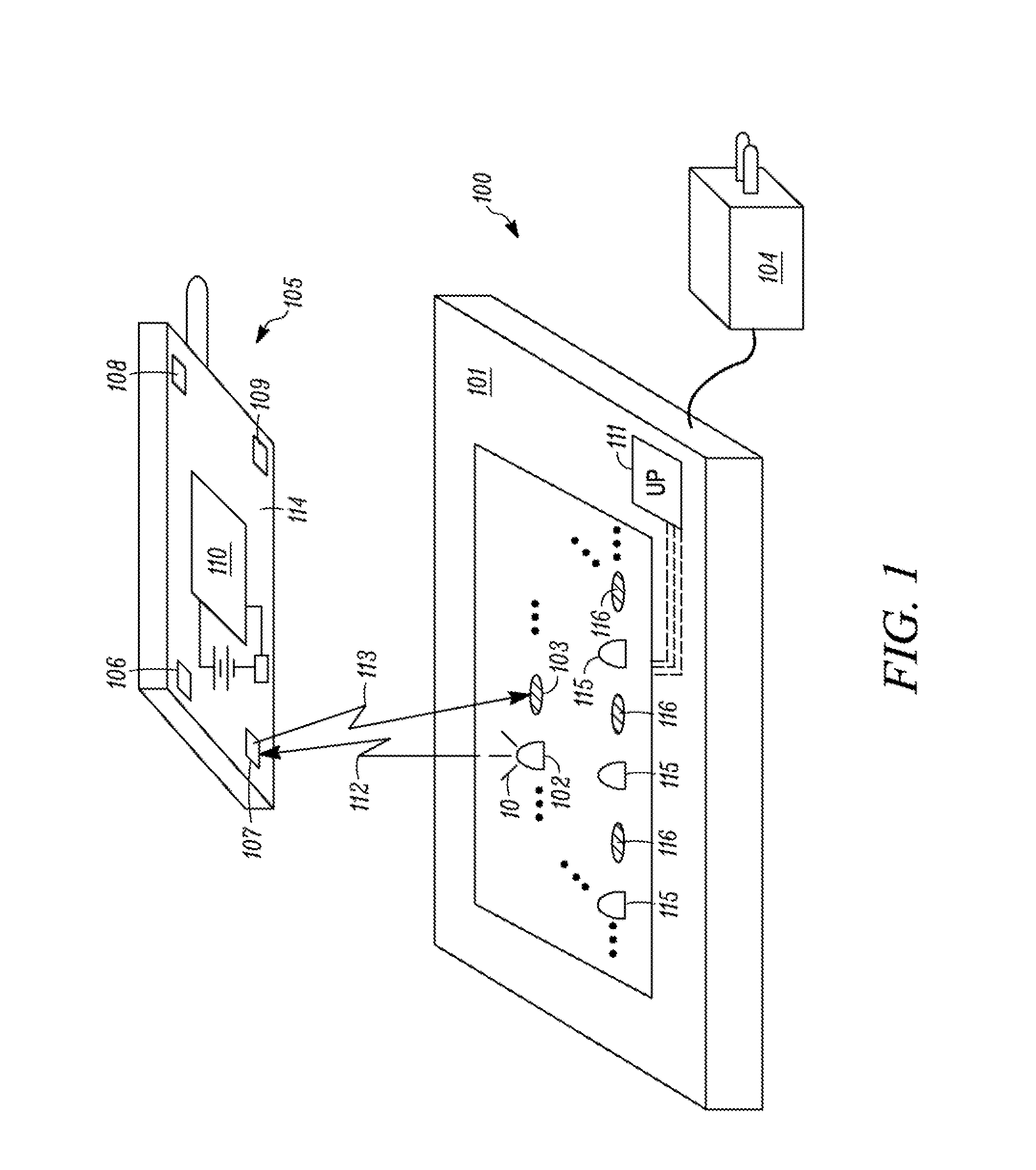
[0018] Before describing in detail embodiments that are in accordance with the present invention, it should be noted that the embodiments reside primarily in combinations of method steps and apparatus components related to a light pad for charging rechargeable batteries used to power electronic devices. Accordingly, the apparatus components and method steps have been represented where appropriate by conventional symbols in the drawings, showing only those specific details that are pertinent to understanding the embodiments of the present invention so as not to obscure the disclosure with details that will be readily apparent to those of ordinary skill in the art having the benefit of the description herein.

[0019] It will be appreciated that embodiments of the invention described herein may be comprised of one or more conventional microprocessors or controllers and unique stored program instructions that control the microprocessors to implement, in conjunction with certain non-proce...


PUM


Abstract

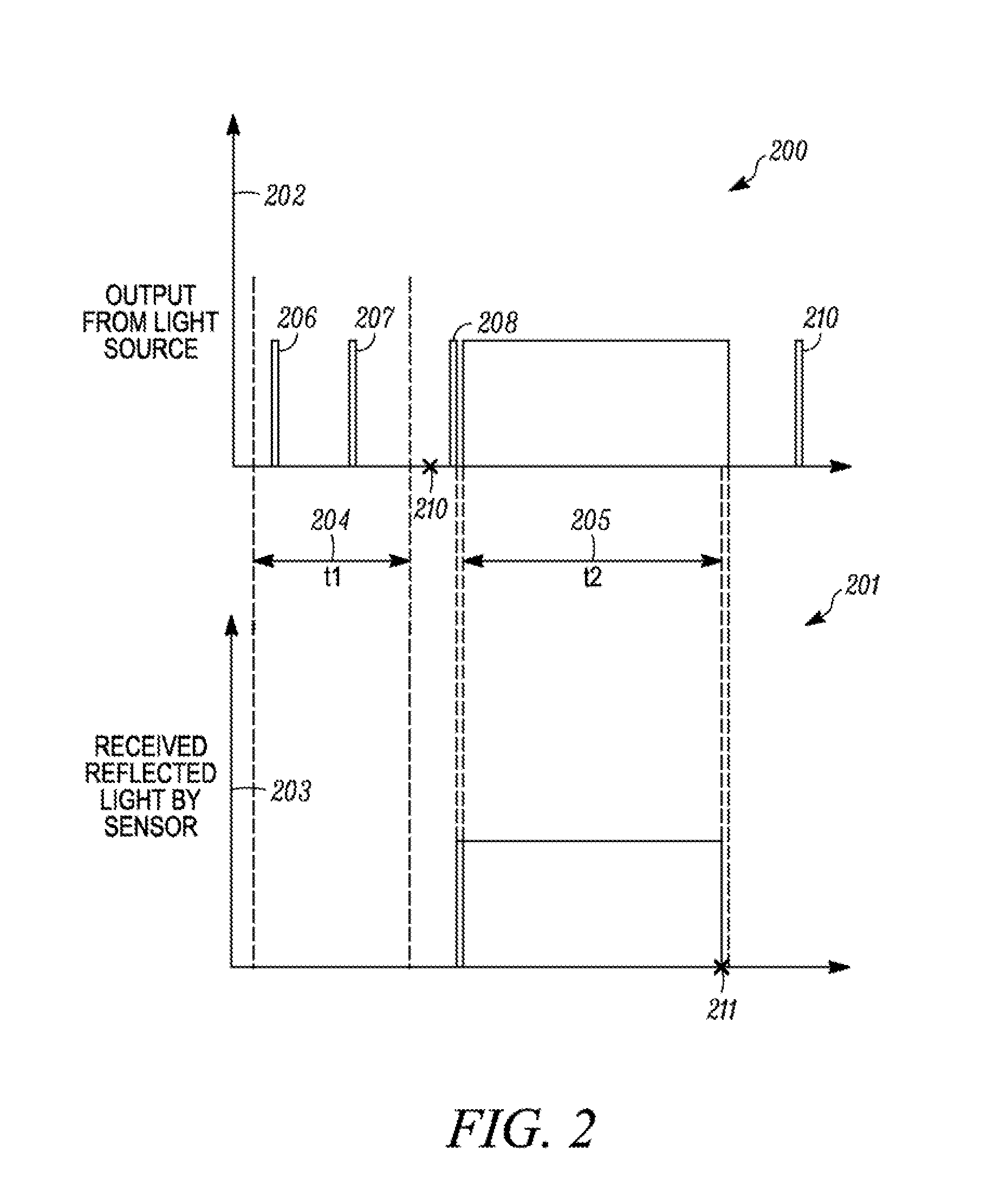
A light emitting charger is provided. The light emitting charger delivers light energy to a portable electronic device having a rechargeable battery. The electronic device is equipped with a photovoltaic energy conversion device that converts the transferred light into an electrical current that can be used to charge the battery. Through alternate communication mechanisms, the electronic device can alert the charger as to when to illuminate the light sources and which light sources to illuminate. The charger is equipped with photo detectors for receiving photo communication from the electronic device. In one embodiment, the charger periodically pulses one or more light sources until it receives light reflected from reflective material disposed along the electronic device. When the reflective light is received, the charger may actuate a plurality of light sources in a predetermined pattern corresponding to the amount or location of the reflective light. In another embodiment, the electronic device is equipped with a photo communication light source, and may communicate with the charger through pulsed light.

Description

TECHNICAL FIELD [0001] This invention relates generally to chargers for electronic devices, and more particularly to a light-emitting charger for contactlessly charging portable electronic devices. BACKGROUND ART [0002] People can be seen with portable electronic devices everywhere. From home to office, from restaurants to sporting events, it seems that almost everyone carries one, or more, portable devices. By way of example, the mobile telephone, once a luxury for the very wealthy, is now quite commonplace. According to the Cellular Telecommunications and Internet Association (CTIA), in 2004 over 182 million people, in the United States alone, used mobile telephones. [0003] Mobile telephones and other devices owe their portability to rechargeable batteries. It is the rechargeable battery that allows the user to move about the world without being tethered to a power outlet. While today's rechargeable batteries may deliver five or more hours of talk time, once their stored energy be...

Claims


Application Information

Patent Timeline
Patent Type & Authority Applications(United States)
IPC IPC(8): H02J7/00
CPCH02J7/355H02J7/35Y02E10/56
Inventor RAMSDEN, MARTIN H.
Owner GOOGLE TECH HLDG LLC
Learn More