
Electrical connecting apparatus

Active Publication Date: 2007-03-29
NIHON MICRONICS
View PDF6 Cites 2 Cited by
  • Summary
  • Abstract
  • Description
  • Claims
  • Application Information

AI Technical Summary

Benefits of technology

[0015] According to the present invention, the first guide is arranged in the lower base, and the device under test is received by the tips of the contactors. Accordingly, even when the upper base or the second guides are displaced against the lower base, the first guide, contactors and device under test are not displaced, and thus displacement of the device under test caused by displacement of the upper base or the second guides is prevented.
[0016] The first guide may be removably mounted in the lower base. By doing so, the first guide can be replaced with an optimal first guide in accordance with the degree of the variety in the dimensional accuracy of the device under test, or the first guide can be replaced with another first guide having different dimensions from those of this first guide for use in testing of another device under test having different dimensions.
[0017] The lower base may have a first hollow opened upward, and the first guide may be formed in a plate shape and be arranged in the first hollow.
[0018] The electrical connecting appar

Problems solved by technology

However, the dimensional accuracy of a sealed IC has slight tolerance resulting from

Method used


Image

  • Electrical connecting apparatus
  • Electrical connecting apparatus
  • Electrical connecting apparatus

Examples


Example

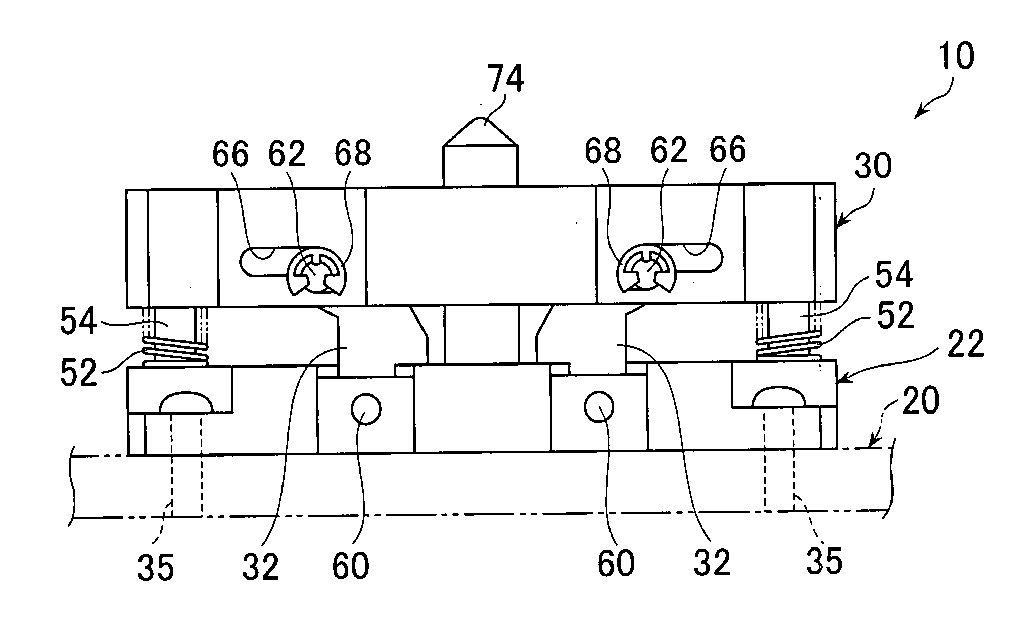
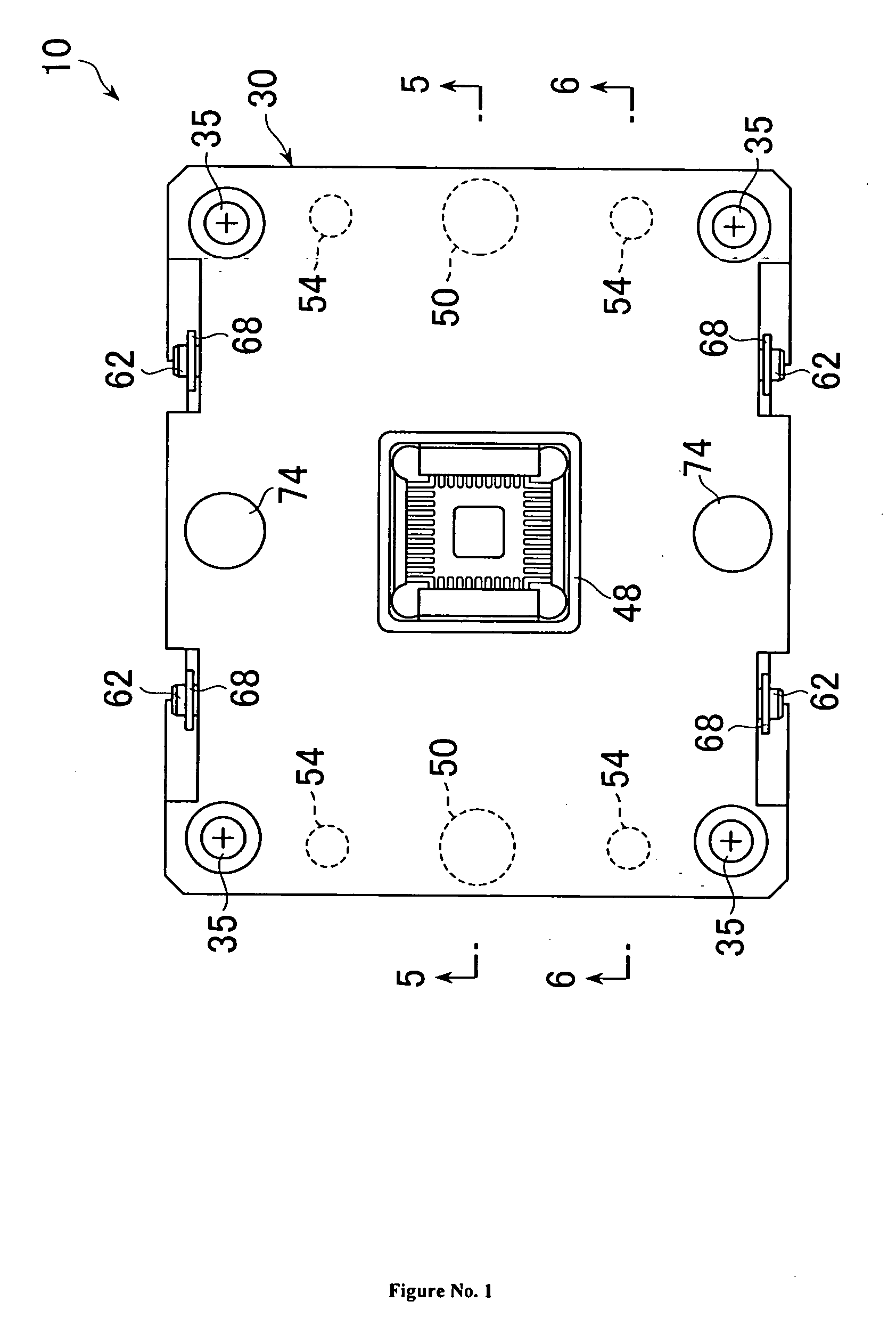
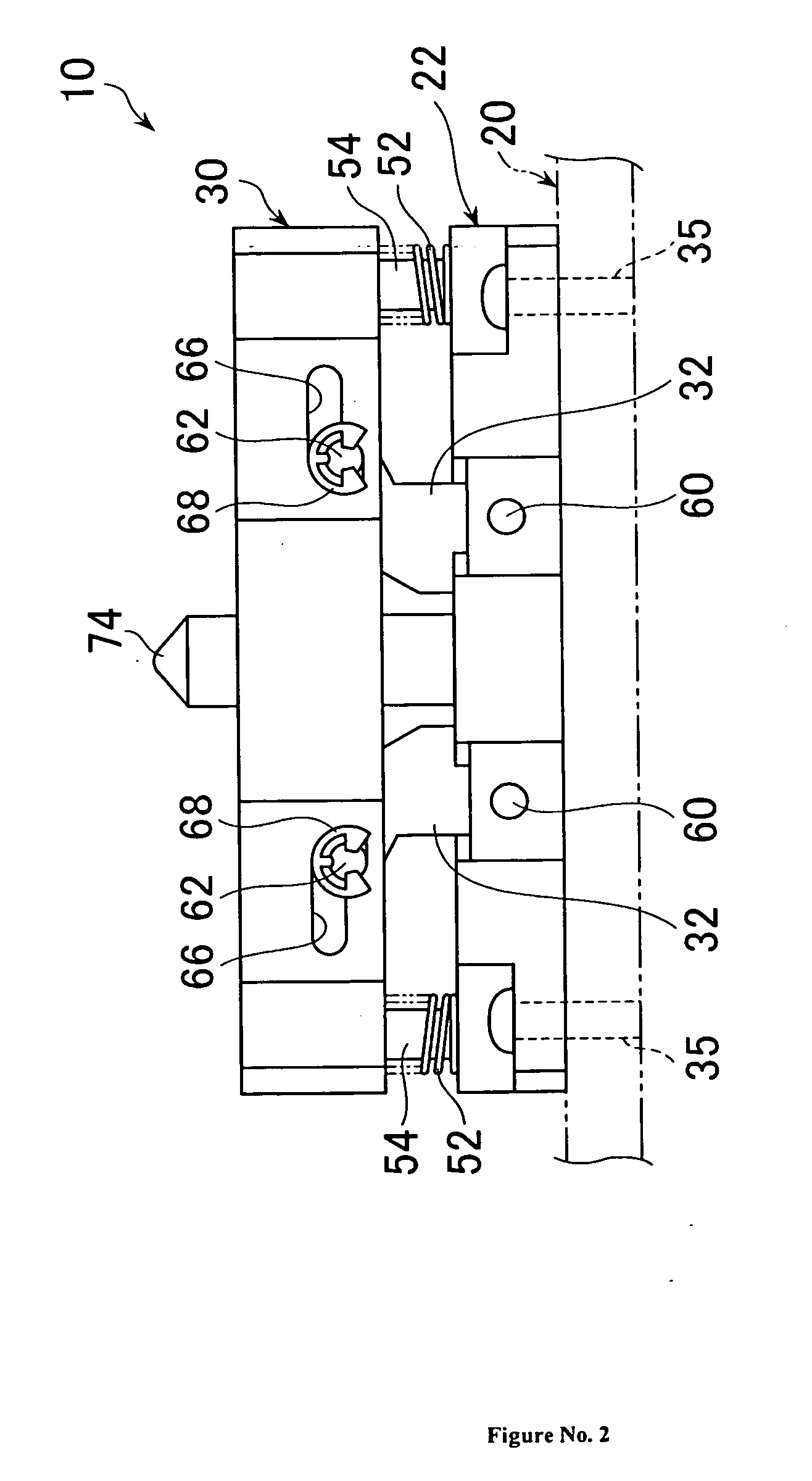
[0033]10: electrical connecting apparatus [0034]12: device under test [0035]14: main body [0036]16: electrode [0037]20: wiring board [0038]22: lower base [0039]24: pedestal [0040]26: contactor [0041]28: first guide [0042]30: upper base [0043]32: second guide [0044]46: first and second hollows [0045]38: slot [0046]76: first and second space [0047]48: opening [0048]50: guide pin [0049]52: elastic body [0050]54: supporting pin [0051]56: swing portion [0052]58: guide portion [0053]62: shaft [0054]66: elongated hole [0055]70: guide surface [0056]72: thrust surface [0057]74: guide pin

[0058] Referring to FIGS. 1 to 8, an electrical connecting apparatus 10 is used for an electrical test to which a semiconductor device is subjected as a device under test 12. The device under test 12 includes a plate-shaped main body 14 packaged or molded in a rectangular flat shape and a plurality of electrodes 16 formed on the lower surface of the main body 14 (refer to FIG. 8).

[0059] These electrodes 16 ...


PUM


Abstract

In an electrical connecting apparatus, a first guide is arranged in a plate-shaped lower base in which the contactors are arranged. The first guide has a first space for guiding a device under test so that its electrodes will contact the tips of contactors and for positioning the device under test against the contactors. The device under test is guided to the first space by second guides and is received and thrust by the tips of the contactors. By doing so, displacement of the device under test caused by displacement of the upper base or the second guides is prevented.

Description

CROSS REFERENCE TO RELATED APPLICATIONS [0001] This application claims the priority benefit of copending PCT / JP2004 / 010247, filed Jul. 12, 2004, which is incorporated herein by reference.TECHNICAL FIELD [0002] The present invention relates to an electrical connecting apparatus for use as an auxiliary apparatus in an electrical test of a semiconductor device such as an integrated circuit. Background Art [0003] In general, an inspection or a test of electrical characteristics of a packaged or molded semiconductor device, more particularly, an integrated circuit (IC,) is performed by utilizing as an auxiliary apparatus an electrical connecting apparatus such as an inspection socket, that is, a test socket to which a semiconductor device is removably attached. [0004] There is provided an electrical connecting apparatus of such a type including an IC holder that can hold an IC as a device under test having a plurality of lead electrodes, and a contactor holder in which a plurality of con...

Claims


Application Information

Patent Timeline
IPC IPC(8): G01R31/26
CPCG01R31/31905
Inventor OSATO, EICHI
Owner NIHON MICRONICS
Learn More